
Computer-Aided Design Software: An Introductory Guide to Solidworks 2021
There’s Fusion 360, AutoCAD, Autodesk Inventor, and many more I wouldn’t be able to list off the top of my head, but trust me when I tell you there is a lot of 3D modeling software out there.
So, why Solidworks? Simple. It’s the industry standard. It’s considered the best of the best.
A few clarifications:
- Solidworks is the standard in the engineering industry, but no, I don’t expect any person reading this to aspire to be an engineer when maybe all you want to do is make fun little designs and 3D print them. Or, if you do aspire to be an engineer and have no experience with Solidworks, read on! This guide is for everyone.
- I understand that some programs are more accessible than others and that Solidworks may be a part of the latter. By no means should this discourage you from picking up skills in any of the CAD software I previously mentioned above!
If you’re reading this, I’m going to assume you’re affiliated with UVA in some way and have access to Solidworks for free, whether on a UVA-owned Windows computer or on a personal Windows computer (available for download here).
As a first-year technologist at the TinkerTank, I struggled with what I wanted to do for my very first workshop. I wanted it to be fun and I wanted the participants to be able to bring something home.
I have a few years of experience with Autodesk Inventor from high school engineering courses and a few months of using Solidworks under my toolbelt so I decided to teach what I thought I could do best out of all the things the Scholars’ Lab offers. I led a beginner workshop in 3D modeling.
View this guide as a written version of the workshop. It is separated into two parts, focused on building a strong foundation and then walking you through a step-by-step tutorial on how to design your own keychain that can be printed in the 3D printing studio at the Robertson Media Center!
Part 1: The Basics
File Types
There are three types of files: Part (.SLDPRT), Assembly (.SLDASM), and Drawing (.SLDDRW)
- Consider part files your standard. It’s the file you create whenever you want to design something.
- Assembly files are multiple part files brought together to create one product. Think of combining different sized lego pieces (your part files) and building a toy car (your assembly file).
- A drawing file is a formal document displaying the front, side, top, and isometric views of a part. Drawing files come with dimensions of your part so someone else can recreate it on their own computer or build it from scratch, like a blacksmith. Think of it as a blueprint for others to look at and understand.
User Interface
Follow along and navigate Solidworks on a computer as I begin to explain the user interface!
When you first open Solidworks, a Welcome Window will pop up and give you three files to choose from. Like I said before, part files are your standard if you just want to make something.
Go ahead and open a part file.
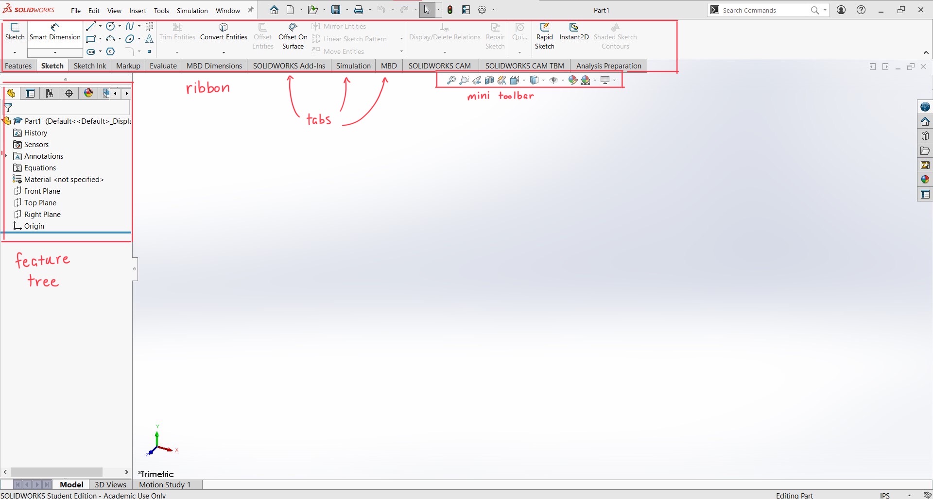
- The ribbon is where you’ll see an array of functions. You only need to worry about the Features and Sketch tabs.
- The feature tree holds information about your part. As you create sketches or features (a 2D sketch turned into a 3D object, or modified in a 3D way), they will be displayed in the feature tree. You’ll begin to see that as you start to design your keychain in Part 2 of this guide.
- The mini toolbar offers several options on how you want to view your part. I don’t use these functions too much, but the View Orientation drop-down menu (sixth from the left) can be helpful.
Keyboard Shortcuts and Mouse Functions
There are a few keyboard shortcuts that will make things so much easier as you’re using Solidworks. These will probably come in handy later in Part 2.
- F key - Fit
- Centers and fits your sketch/object to the computer screen
- Ctrl 7 - Isometric View
- Gives you the isometric view of your part
- Ctrl 8 - Normal To
- Reorients your view to be aligned with the sketch or the coordinate system
- Ctrl Z - Undo
- Undo previous action(s)
- Esc key - Escape
- Helpful for when you’re using any of the sketch tools (line, rectangle, circle, etc.)
It’s wise to use a mouse when you’re modeling in CAD software because it adds more speed and precision. Using a mouse also comes with a few other functions.
- Zooming in and out
- It can be a little finicky, especially if you’re not used to it.
- Wherever your cursor is on the screen, that’s where it will zoom in and out—the zoom function is not centered in the middle of your screen
- It can be easy to lose your sketch/object, but don’t worry! Hit the F key or Ctrl 7 to fix the issue!
- Try experimenting with this in Part 2.
- Rotating your sketch/object
- You can hold down the scroll wheel on your mouse and move around to rotate your sketch or your object in all directions.
- This can also be a little tricky to master at first so if you can’t reorient it the way you want to, remember you always have those keyboard shortcuts to realign your sketch or feature.
Part 2: Designing a Part
Three Ways of Starting a Sketch
Make sure you’re in the Sketch tab, and pay attention to what’s highlighted in the picture below and what appears on your screen.
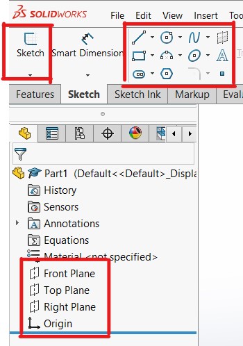
- Click on Sketch icon (highlighted top left) > Select a plane (appears center of screen) > Select sketch tool (highlighted top right)
- Select a plane (highlighted bottom) > Select sketch tool (highlighted top right)
- Select sketch tool (highlighted top right) > select a plane (appears center of screen)
A few notes:
- Choosing what plane to start your sketch comes with practice and your intuition.
- If you’re familiar with what the end result will look like, it might make more sense to select the front plane over the top plane, or the top plane over the right plane, etc.
- As for which way to start a sketch, my brain defaults to option 3—it’s all preference
Concepts
Under Defined and Fully Defined
- When you’re sketching, you’ll see that the lines are blue (some may be black).
- That means those lines are under defined—they are not dimensioned or positioned.
- When a sketch is fully defined, all the lines are black.
- As you design your keychain, take note of the blue and black lines. Also look at the bottom right corner of your screen, and it will either say “Under Defined” or “Fully Defined.”
- To make a sketch fully defined, you must dimension and position every shape or line using the Smart Dimension tool.
Good Technique
- When you begin a sketch, always attach your first shape or your first line to the origin point!!!
- After you’re done sketching and you’re ready to turn it into a 3D object, make sure your sketch is fully defined!!!
These key points will help you tremendously in the long run, especially as you start to design more complex parts, and they will be reiterated for clarity in the following steps.
- Whichever way you choose to start a sketch, select the top plane and create a rectangle of any size attached to the origin.
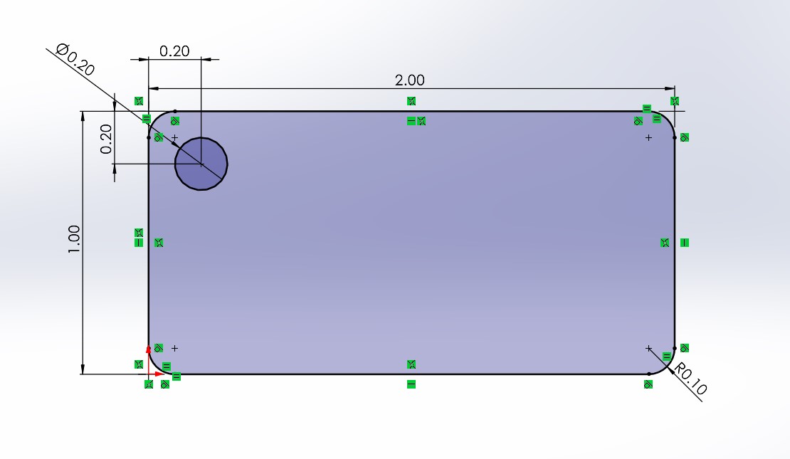
- Fully define the sketch by selecting the Smart Dimension tool (next to the Sketch icon in the ribbon). Click the left or right side of the rectangle, drag your cursor out, and click again. Make the dimension 1 inch. Click the top or bottom side of the rectangle, drag your cursor out, and click again. Make the dimension 2 inches. The rectangle should now be fully dimensioned (all the lines are black; the bottom right corner of your screen says “Fully Defined”) and 2x1 inches.
- Round the edges of the rectangle by clicking on the Fillet sketch tool and hovering over and clicking the edges of the rectangle. Press enter or click the green check mark on the left side of the screen once all four corners have been selected.
- Select the Circle sketch tool and draw a circle anywhere on the surface of the rectangle.
-
Fully define the circle by dimensioning the radius and positioning the circle with respect to the rectangle. Use the Smart Dimension tool and click on the edge of the circle, drag your cursor out, and click again. Set the diameter equal to 0.20 inch. To position the circle, use the Smart Dimension tool and click on the edge of the circle, then click on the left side of the rectangle, and set the distance from the center of the circle to the edge of the rectangle to 0.20 inch. Repeat this process with the top side of the rectangle with the same measurement.
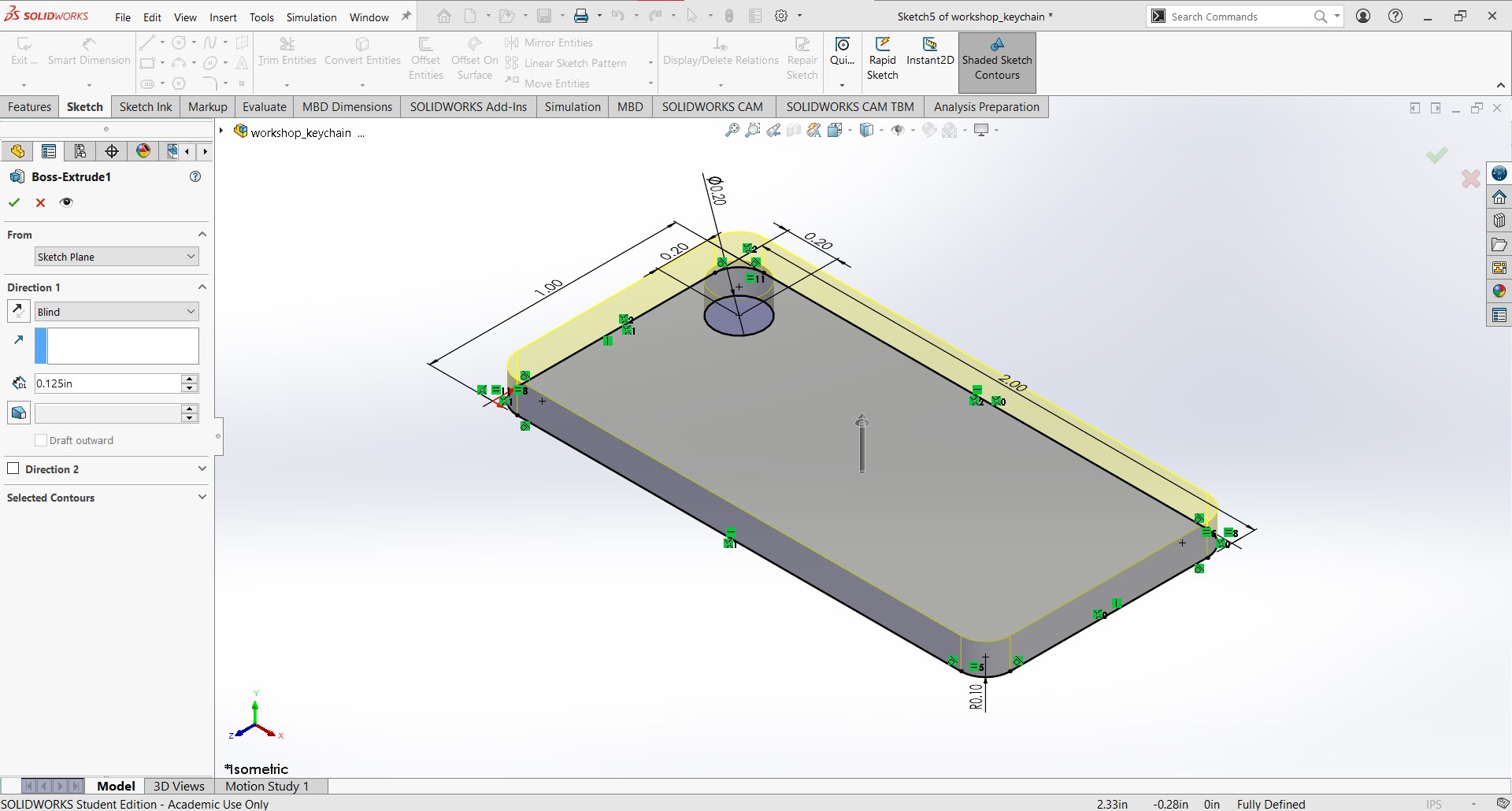
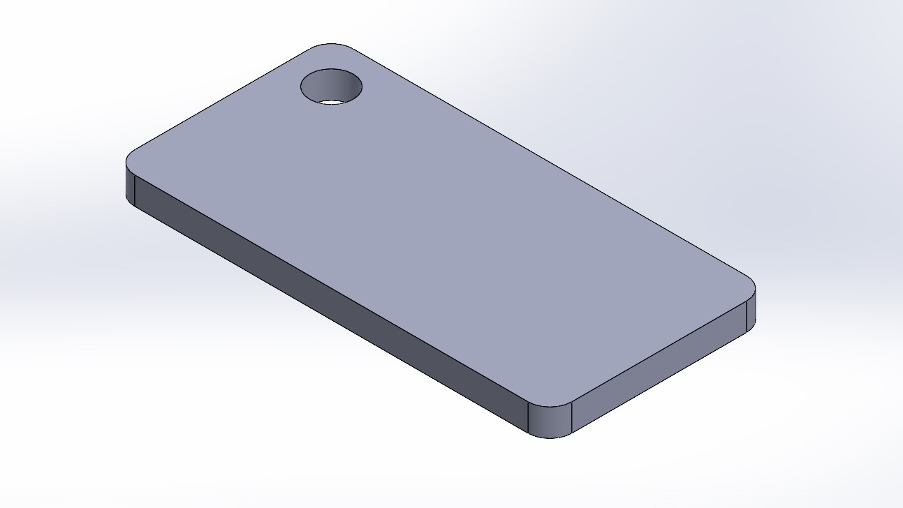
- Click the Features tab in the ribbon and click the Extruded Boss/Base icon. Extrude the rectangle by 0.125 inch.
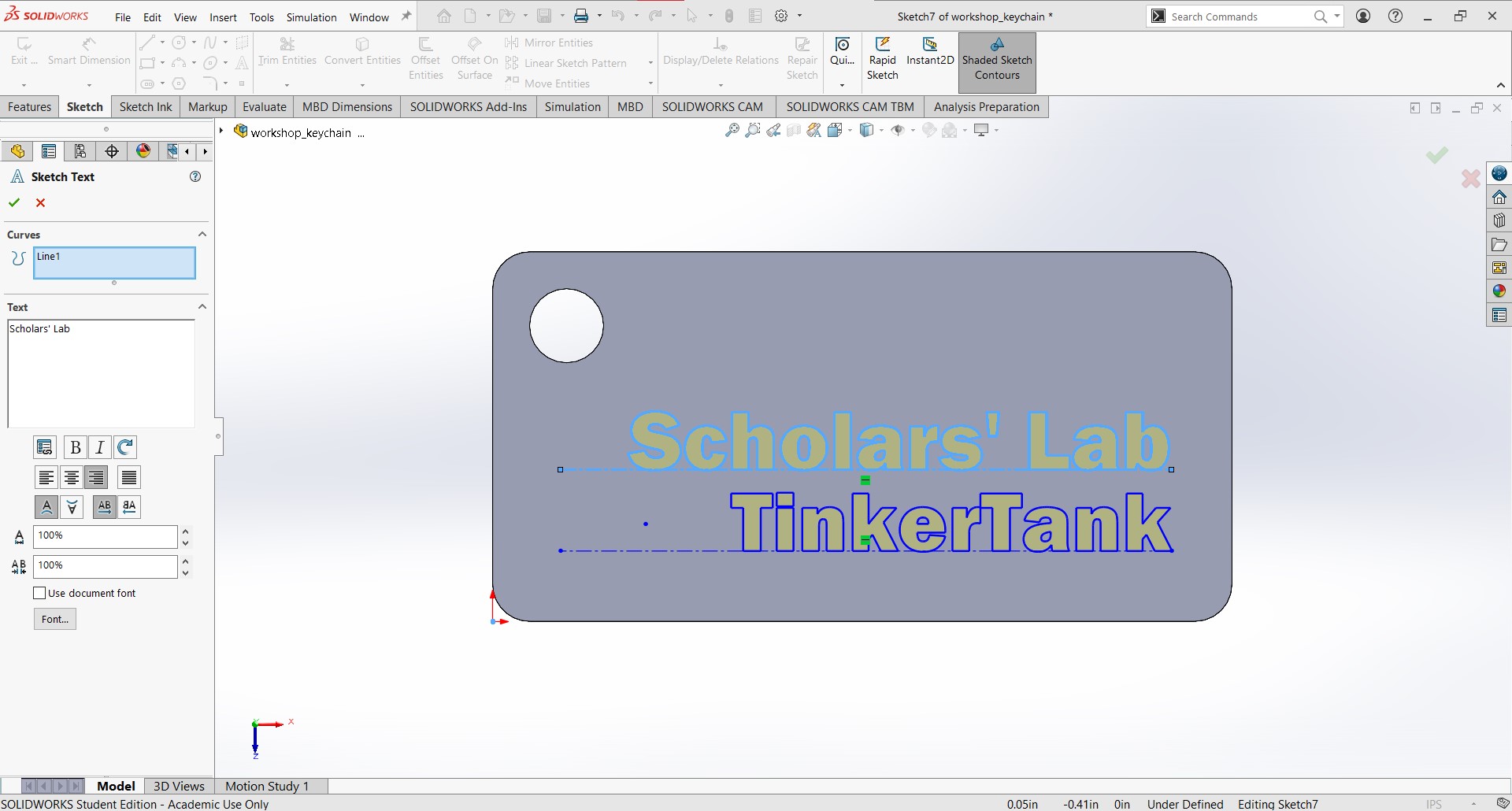
- It’s now time to add text. Centerlines are a perfect way to position your text on a surface of a 3D object. Head over to the Sketch tab and start a new sketch. The plane you are now choosing is the top surface of the keychain. In the drop-down menu of the Line sketch tool, select Centerline. Draw a line or two anywhere you would like to have your text placed.
- Once you have centerlines, select the Text sketch tool and a new menu will appear on the left side of the screen. Notice the Curves box is highlighted. Select one centerline where you would like your text to be. Then type into the textbox. To edit the font or size, first uncheck “Use Document Font.” (When printing such small text, it’s best to avoid fancy fonts and use as much surface area as possible.)
- Repeat the same process if you have more than one centerline.

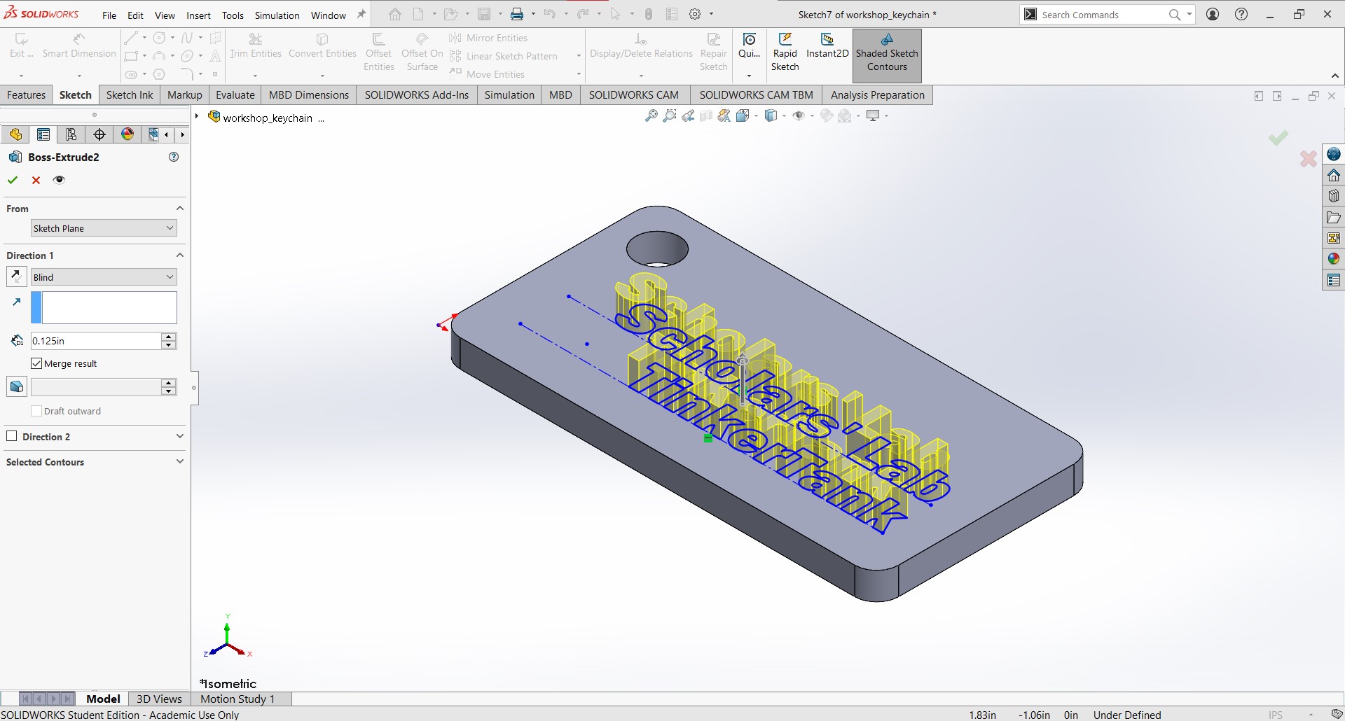
- Once you’re finished with the text, head over to the Features tab, click on Extruded Boss/Base, and extrude it by 0.125 inch.
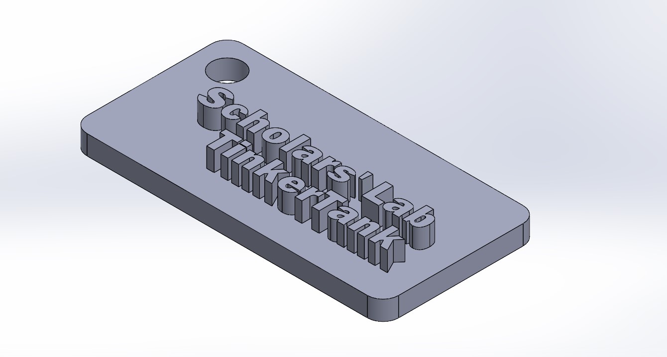
- You now have a personalized keychain that’s ready to be printed!
I hope this guide was helpful and a jump in the right direction. Learning new things can be tricky, especially when you can’t watch someone do it first, but I have faith in all of you!!!
If you would like to gain access to the 3D printers at the Robertson Media Center at Clemons Library, print your keychain and so much more, complete the online and in-person orientation!