
LED Watch Making
LED Watch Making
 [A watch?]
The Idea
This project started as an idea over three years ago when I saw a watch someone was wearing at a conference I was attending, ISAM 2016, the International Symposium of Academic Makerspaces. The watch I saw was a wooden square. The face was simply holes at each hour, with LED lights underneath to illuminate the hours, minutes and seconds. I figured that would be an easy design to replicate.
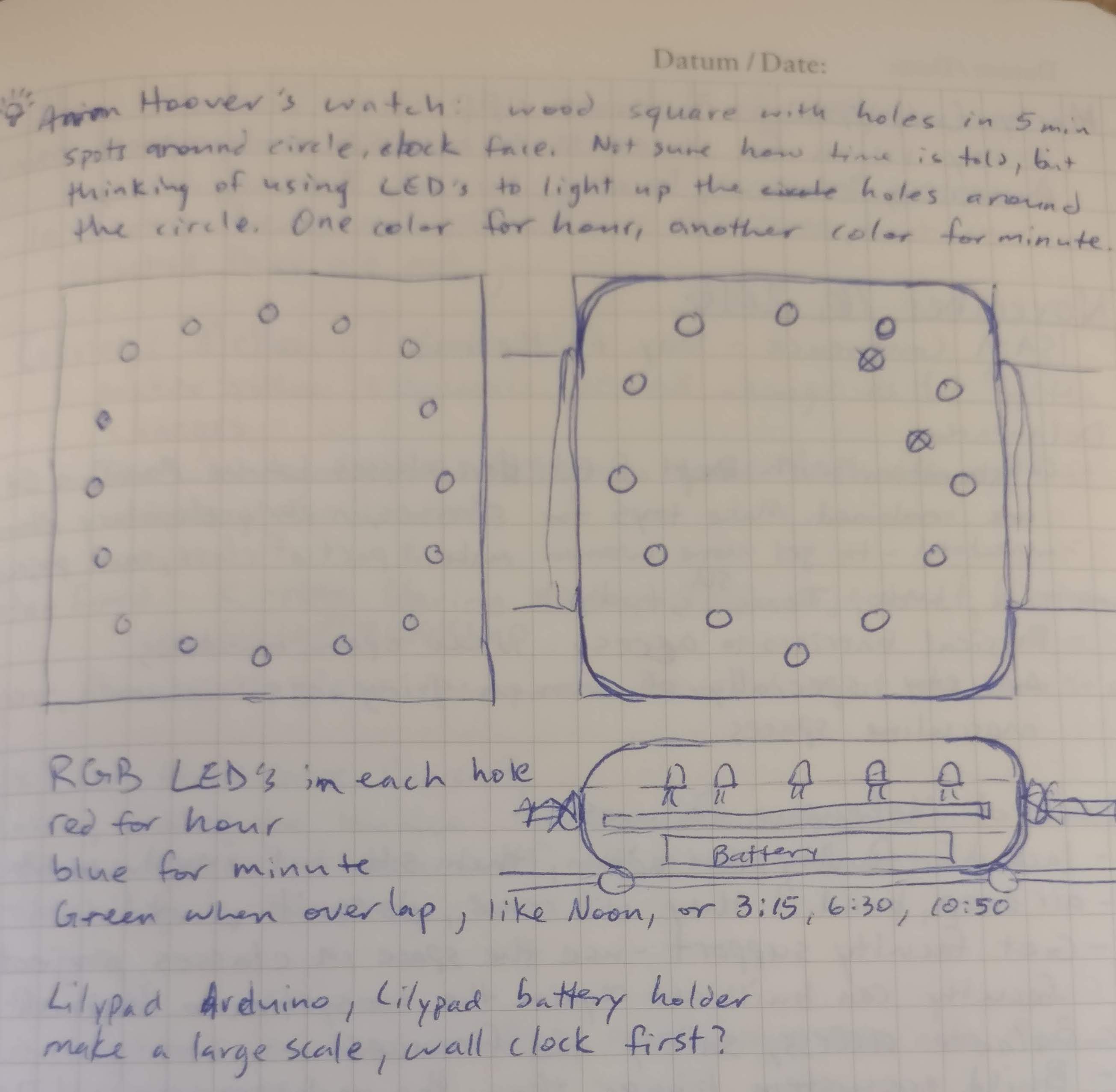 [First sketch of an LED watch in November 2016]
An attempt later the next year ended in failure, as the LEDs and boards I purchased proved to be unresponsive and too difficult to get working. The boards did not solder together well, and the code was hard to write with little documentation.
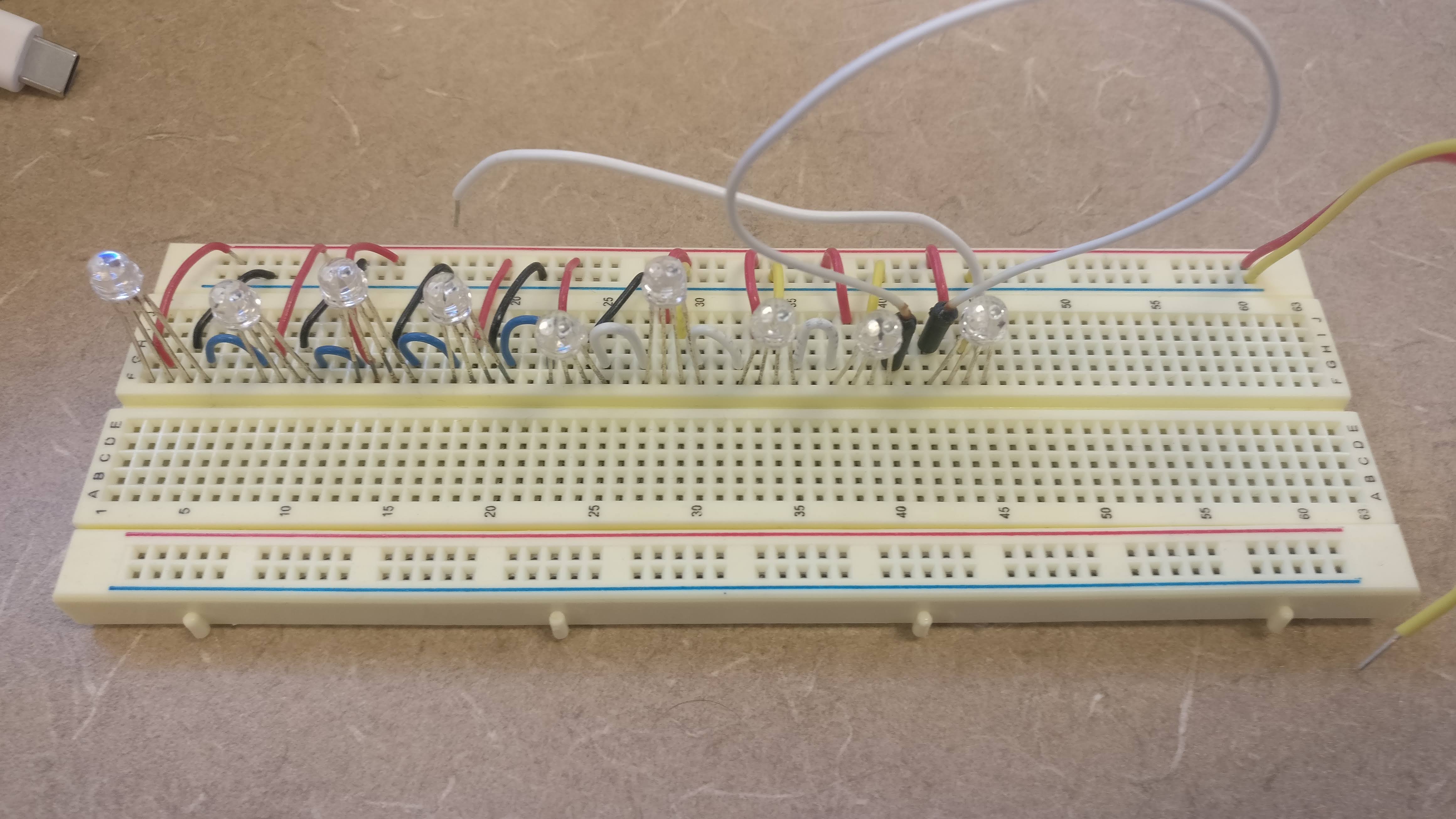 [First attempt with just LEDs]
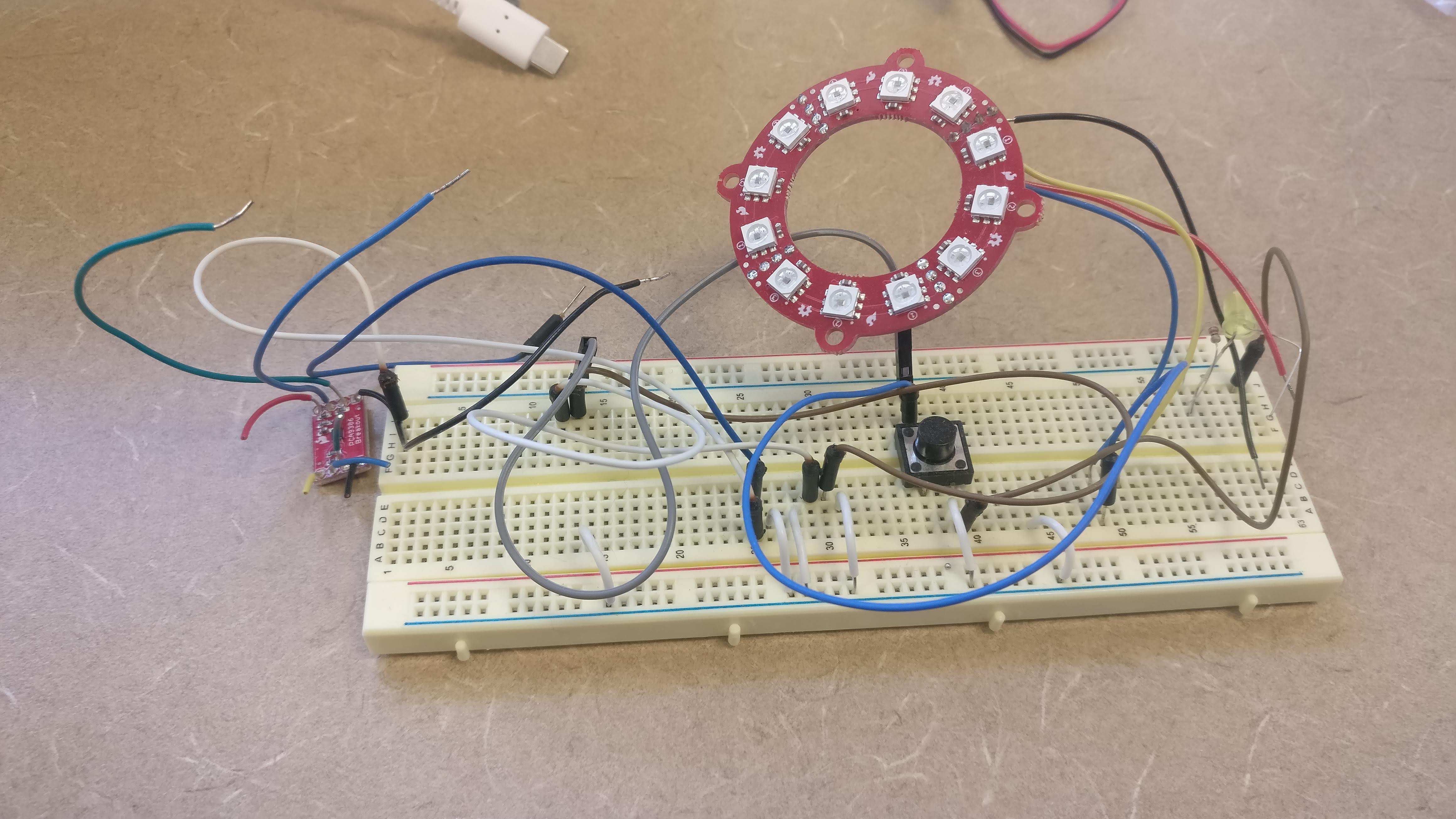 [2nd attempt…]
This time, I was able to find some parts from Adafruit.com that simplified the project immensely. They even had a tutorial for creating a watch! https://learn.adafruit.com/flora-geo-watch/
The Guts
The process of soldering the pieces together was quite simple. The only problem here was getting the wires soldered on in the right lengths and oriented in the right way for the boards to sit on top of each other correctly. I did also run into an issue where I had wrapped the wire around the holes in the board, and then soldered them in place. This proved to be an issue when trying to make a case that fit the dimensions of the board. I had to clip the excess solder and wires from the edge of the board.
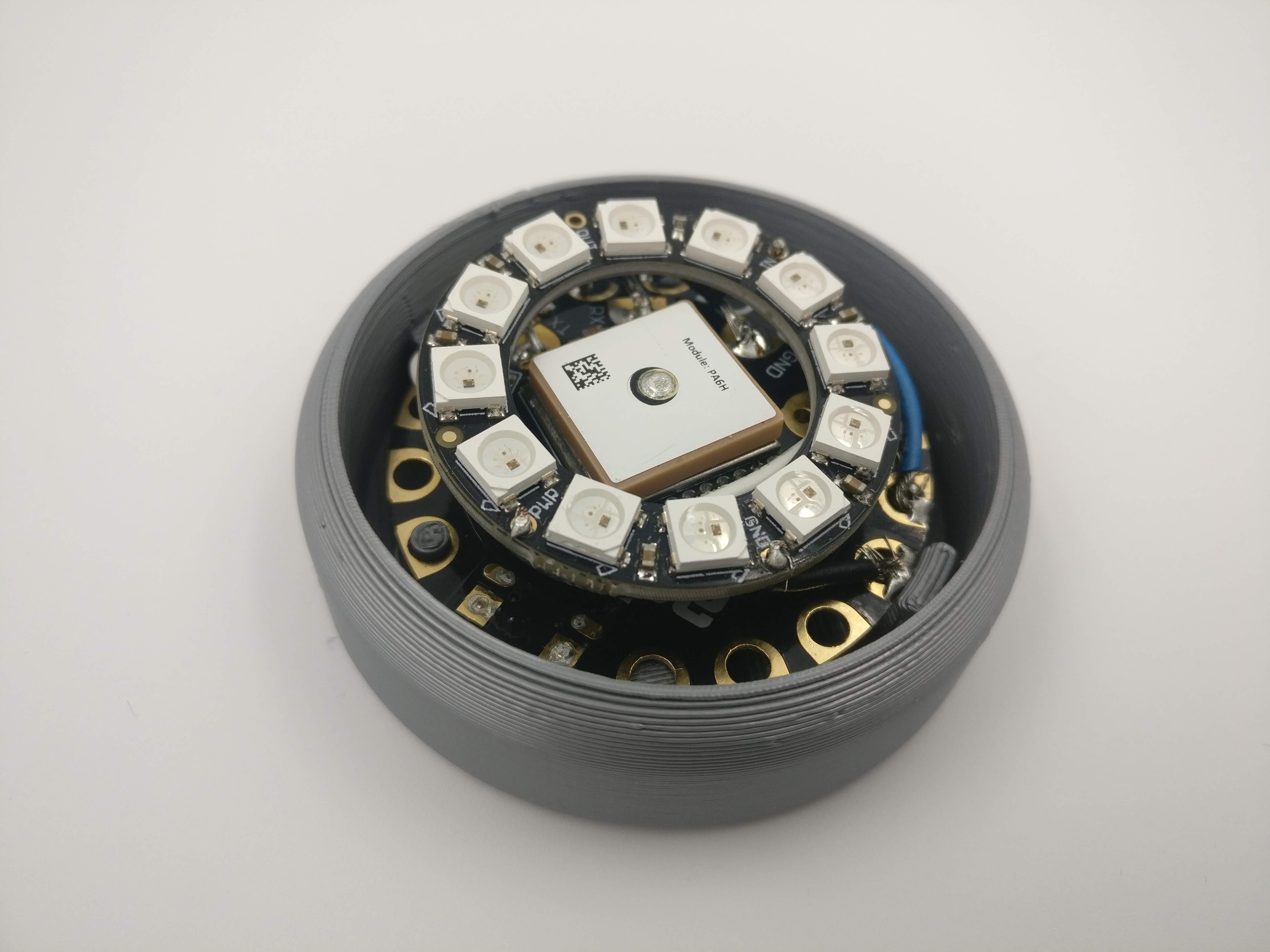
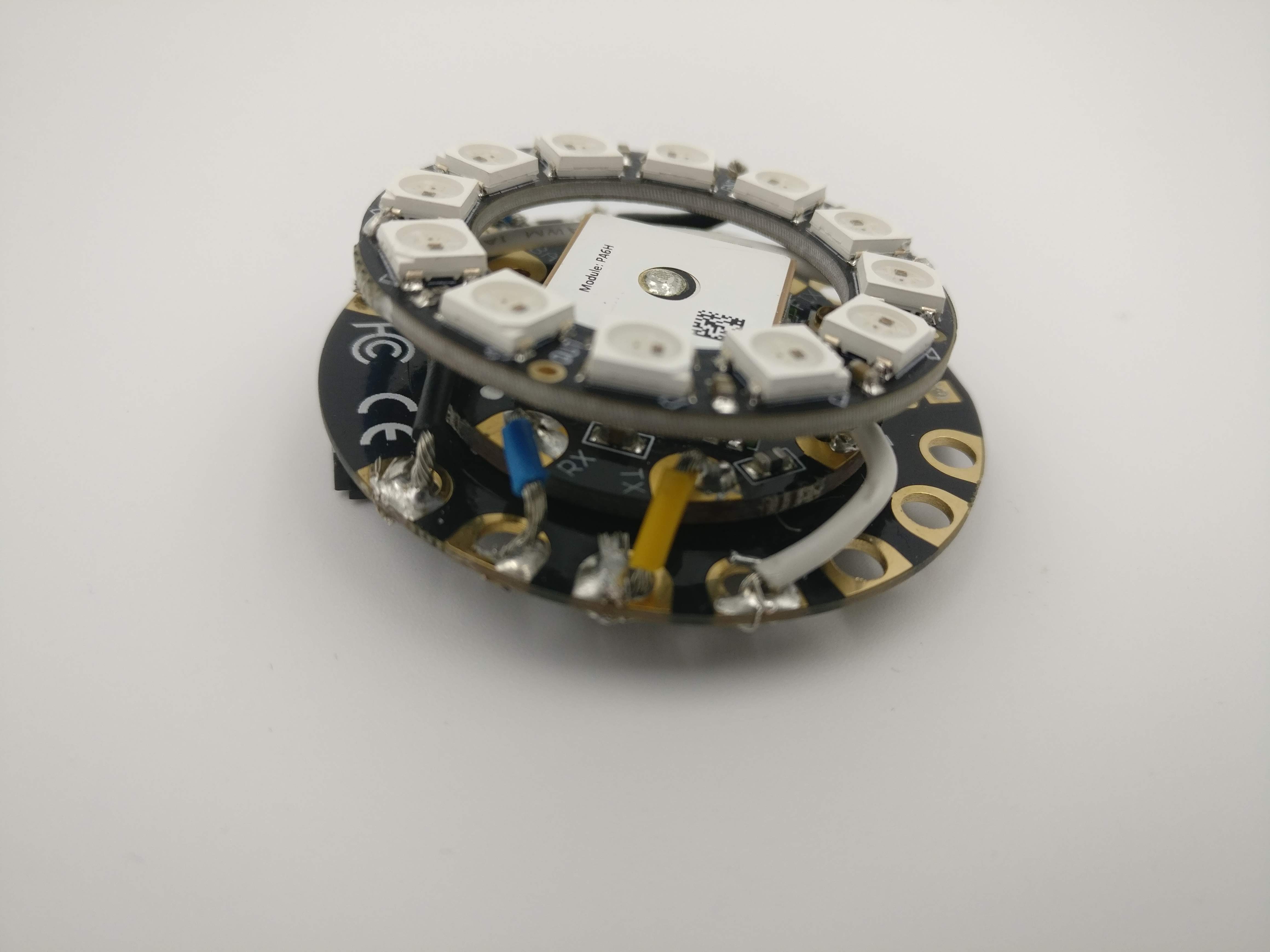 [The guts of the watch, assembled FLORA, GPS module, and NeoPixel Ring]
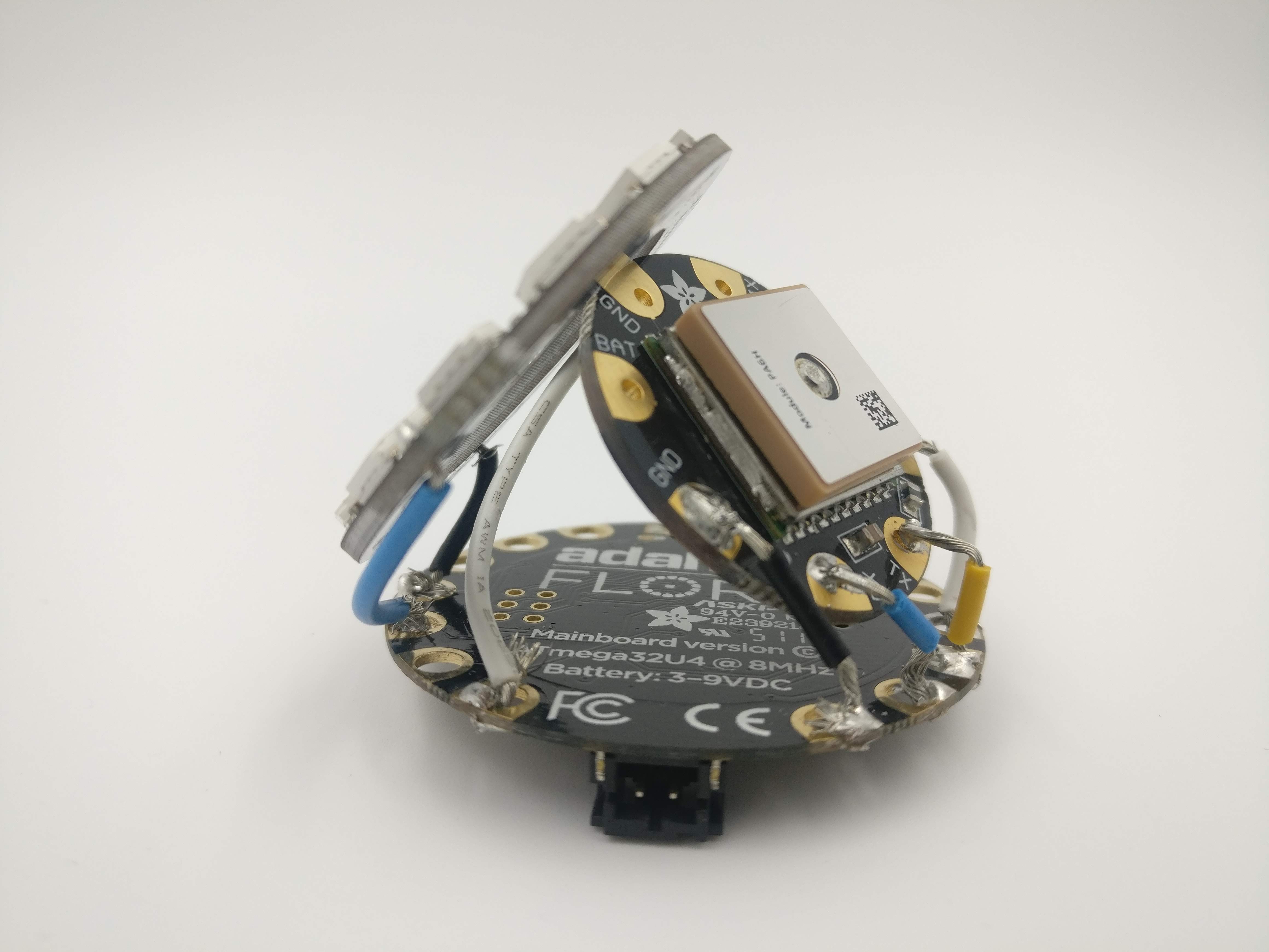 [The assembled FLORA, GPS module, and NeoPixel Ring, exploded view 1]
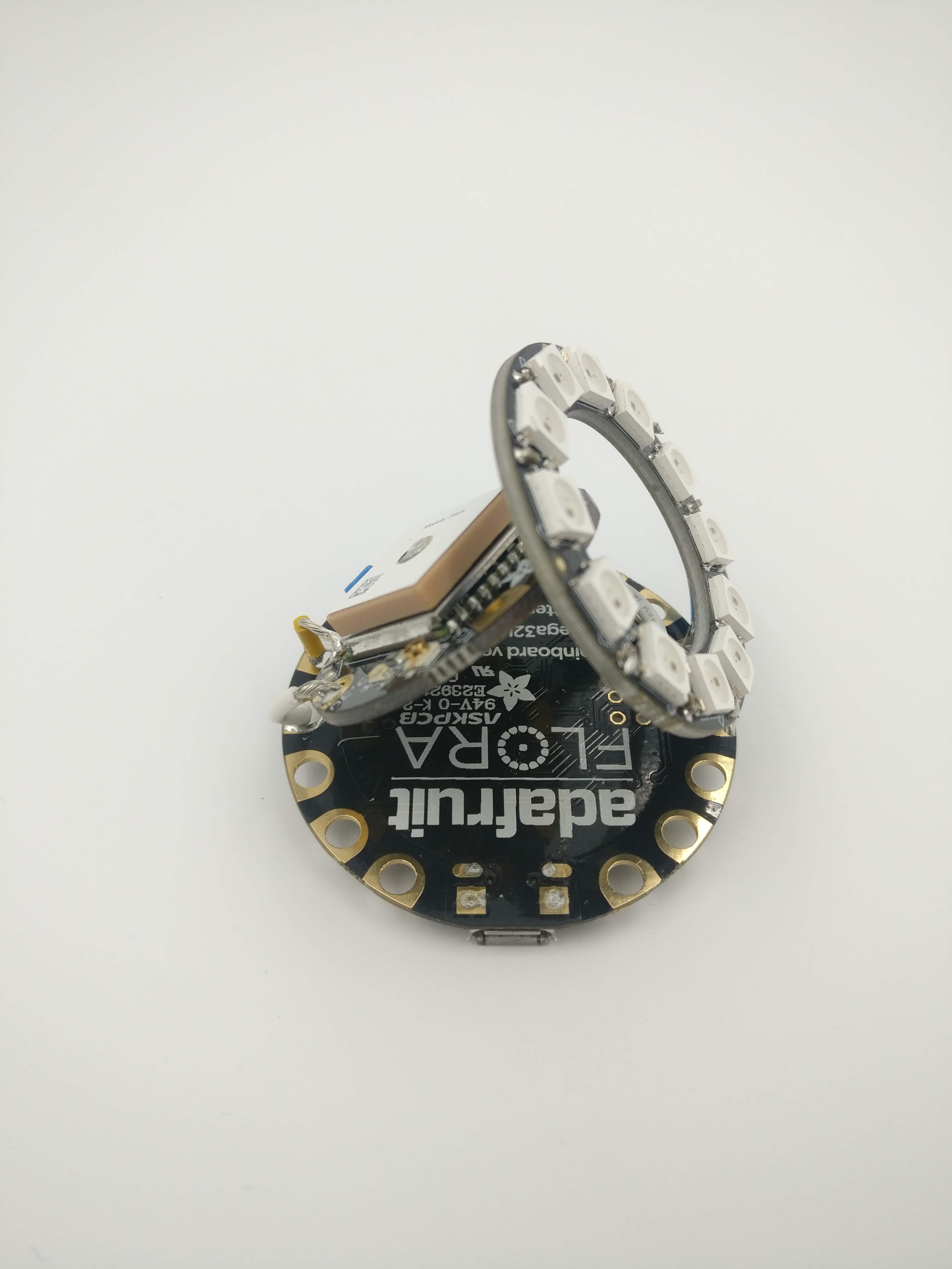 [The assembled FLORA, GPS module, and NeoPixel Ring, exploded view 2]
The Code
The Arduino code was pretty simple. I started by writing generic code that would turn on a certain LED if a number passed to a function was within a certain range. For example, LED 0 turns on when the number is between 0 and 4 (inclusive), LED 1 turns on when the number is between 5 and 9 (inclusive). With that code figured out, I read documentation and examples to pull the hour, minute, and second from the GPS sensor. Then I plugged that value from the GPS sensor into the function explained above. That easily generates a green light for second, red light for the minute and blue light for the hour. The second and minute are set in increments of five. So each LED is in turn illuminated for five seconds green. This proved to be a work in progress, too, because the GPS unit did not get a good reading on the satellites, and did not update to the correct time.
See below for the code so far, or here: https://github.com/ammonshepherd/led-watch/tree/master/watch_code
The Case
With the code (mostly) working correctly. I started designing the case. The original idea of a wood case was too much to handle for the moment. So I went with a 3D printed case. I designed the case in Fusion 360. The original design is a cylinder with cut outs for the micro-USB port and the JST port. I went through eight iterations before deciding that the entire thing should be encompassed in the case, with no holes, in order to better support the PCB and to better incorporate the battery. I found a tutorial on Youtube that shows how to create the support structure that I’m looking for, so I’ll be following that to design a better case, while also incorporating a way to include a watch strap.
 [First case attempt]
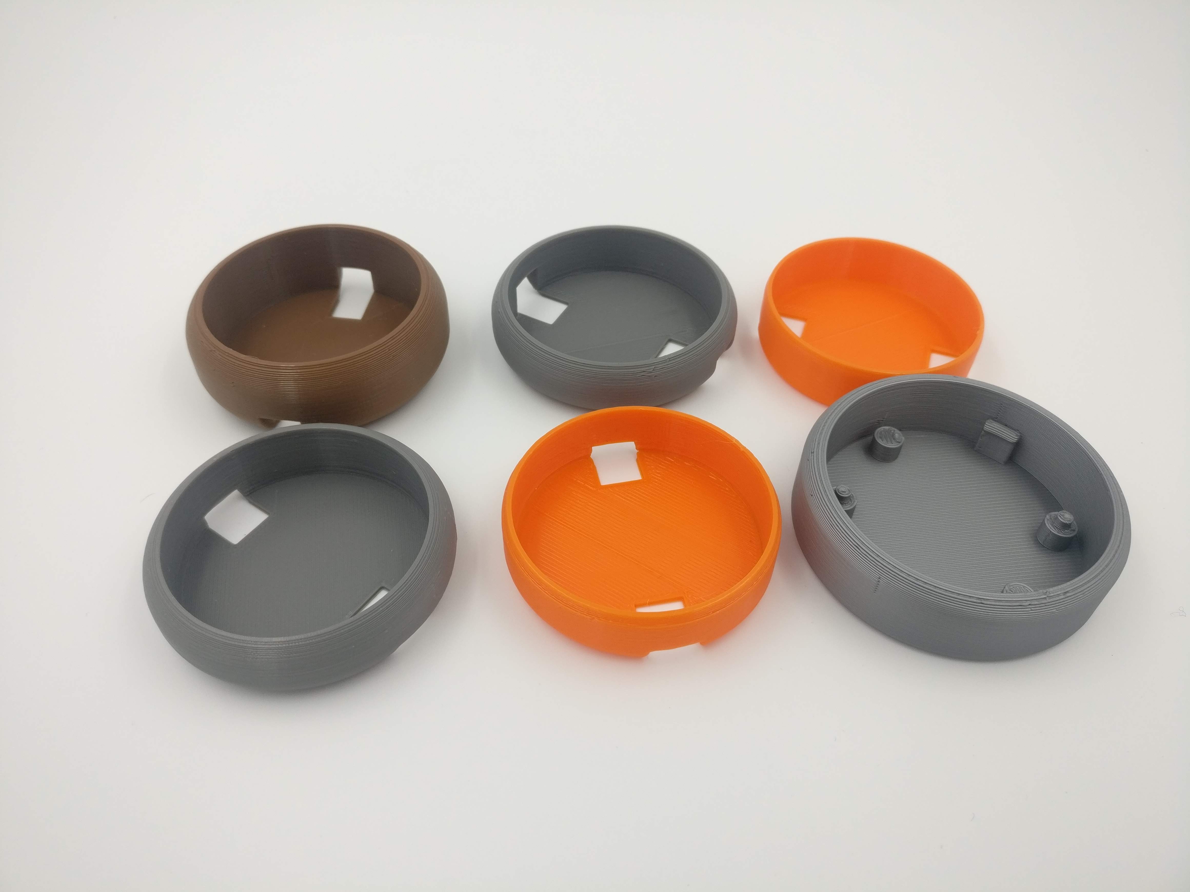 [Various itterations of the case]
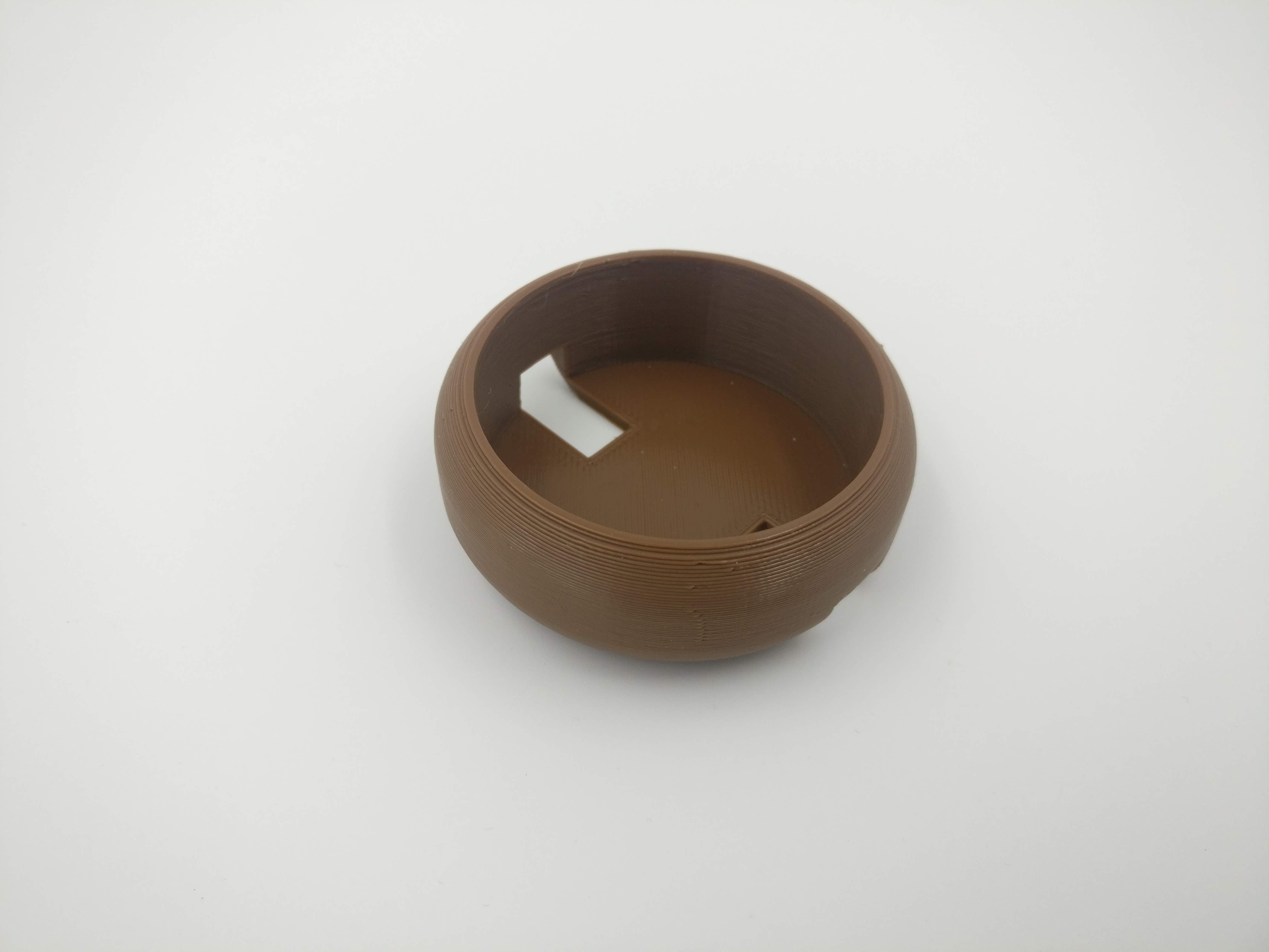
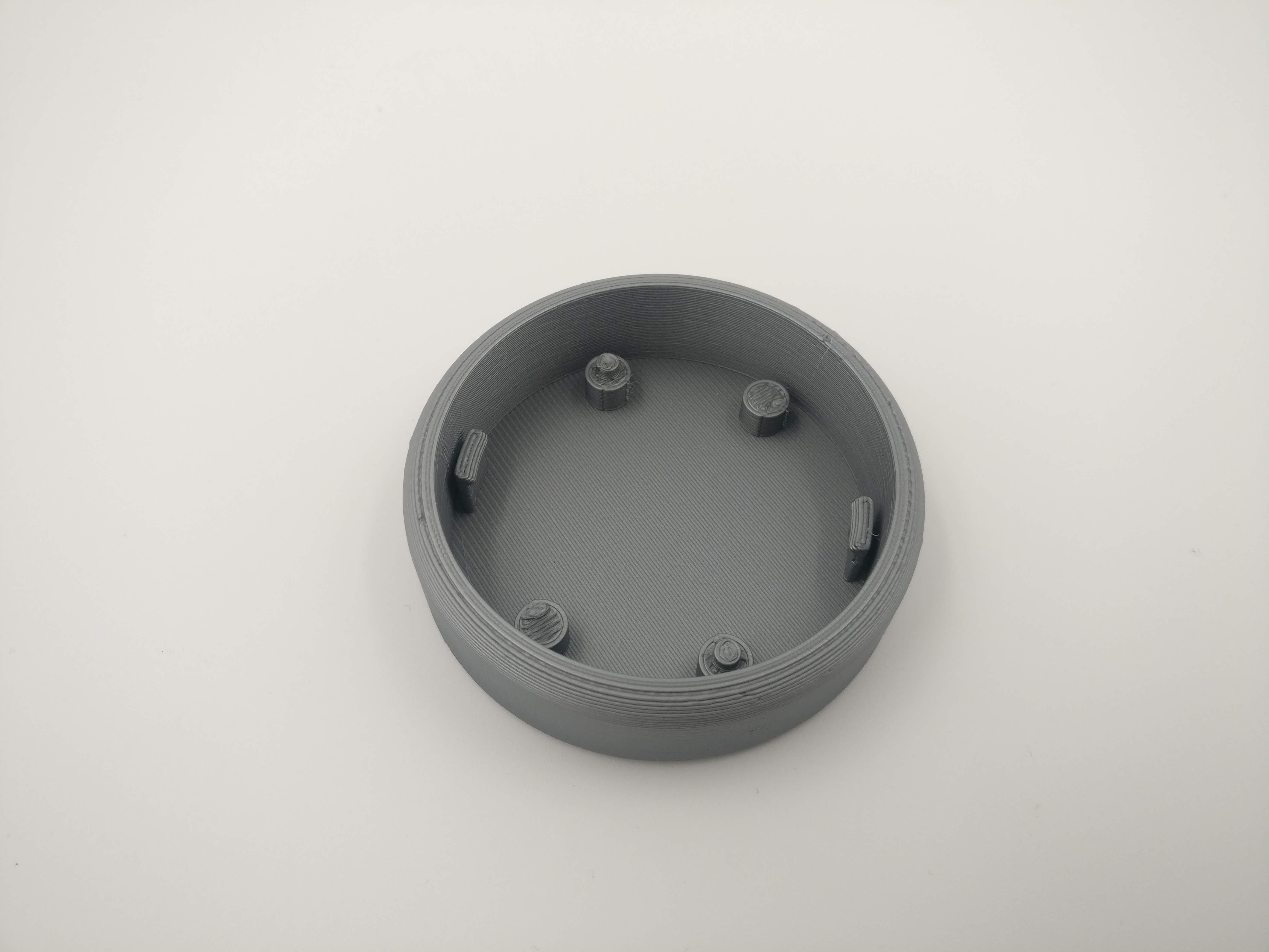 [The latest version of the case]
The next steps are to:
- Fix the code so it accurately tells time and gets the correct time from the GPS module.
- Design and make a better case, with acrylic top.
- Design and create a watch band.
Resources:
- Adafruit watch
- NeoPixel Ring
- FLORA Wearable
- GPS module
- Battery and charger
- Tutorial for designing the case
Arduino Code
/*
   Author: Ammon Shepherd
   Date: November 21, 2019

   Display the time on an Adafruit NeoPixel Ring with Adafruit GPS module and Flora

   Parts:
     - NeoPixel Ring: https://www.adafruit.com/product/1643
     - Flora Wearable Ultimate GPS Module: https://www.adafruit.com/product/1059
     - Flora Main Board: https://www.adafruit.com/product/659

    NeoPixel Ring Pin Layout:
     Time : PIN
     - 12 : 0
     - 01 : 1
     - 02 : 2
     - 03 : 3
     - 04 : 4
     - 05 : 5
     - 06 : 6
     - 07 : 7
     - 08 : 8
     - 09 : 9
     - 10 : 10
     - 11 : 11

*/

#include <Adafruit_NeoPixel.h>
#include <Adafruit_GPS.h>

#define GPSSerial Serial1
#define LED_PIN 6
#define LED_COUNT 12

Adafruit_NeoPixel strip(LED_COUNT, LED_PIN, NEO_GRB + NEO_KHZ800);

uint32_t SECONDS_COLOR = strip.Color(0, 230, 0);
uint32_t MINUTES_COLOR = strip.Color(230, 0, 0);
uint32_t HOURS_COLOR = strip.Color(0, 0, 230);


Adafruit_GPS GPS(&GPSSerial);
// Set to false to not send serial data
#define GPSECHO true

uint32_t timer = millis();

void setup() {

  Serial.begin(115200);
  Serial.println("LED Watch Code");

  // Start the GPS stuff
  GPS.begin(9600);
  GPS.sendCommand(PMTK_SET_NMEA_OUTPUT_RMCONLY);
  GPS.sendCommand(PMTK_SET_NMEA_UPDATE_1HZ);
  GPS.sendCommand(PGCMD_ANTENNA);
  delay(1000);
  GPSSerial.println(PMTK_Q_RELEASE);


  // Start the LED ring off
  //Serial.begin(9600);
  strip.begin();
  strip.show();
  strip.setBrightness(3);


}

void loop() {

  char c = GPS.read();

  // debug info, set above
  if (GPSECHO) {
    if (c) {
      Serial.print(c);
    }

    Serial.print("hour: ");
    Serial.println(GPS.hour, DEC);

    Serial.print("minute: ");
    Serial.println(GPS.minute, DEC);

    Serial.print("second: ");
    Serial.println(GPS.seconds, DEC);

    Serial.print("day: ");
    Serial.println(GPS.day, DEC);

    Serial.print("month: ");
    Serial.println(GPS.month, DEC);

    Serial.print("year: ");
    Serial.println(GPS.year, DEC);

    if (GPS.newNMEAreceived()) {
      Serial.println(GPS.lastNMEA());
      if (!GPS.parse(GPS.lastNMEA())) {
        return;
      }
    }

  }


  show_time(GPS.hour, "hours");
  show_time(GPS.minute, "minutes");
  show_time(GPS.seconds, "seconds");


  /*
    for (int s = 0; s < 60; s++) {
      seconds(s);
      delay(1000);
    }
  */

}

void show_time(int t, String color) {
  int led;
  if ( t >= 0 and t < 5) {
    led = 0;
  }
  if ( t > 4 and t < 10 ) {
    led = 1;
  }
  if ( t > 9 and t < 15 ) {
    led = 2;
  }
  if ( t > 14 and t < 20 ) {
    led = 3;
  }
  if ( t > 19 and t < 25 ) {
    led = 4;
  }
  if ( t > 24 and t < 30 ) {
    led = 5;
  }
  if ( t > 29 and t < 35 ) {
    led = 6;
  }
  if ( t > 34 and t < 40 ) {
    led = 7;
  }
  if ( t > 39 and t < 45 ) {
    led = 8;
  }
  if ( t > 44 and t < 50 ) {
    led = 9;
  }
  if ( t > 49 and t < 55 ) {
    led = 10;
  }
  if ( t > 54) {
    led = 11;
  }

  strip.clear();
  uint32_t display_color;
  if (color == "hours") {
    display_color = HOURS_COLOR;
  } else if (color == "minutes") {
    display_color = MINUTES_COLOR;
  } else if (color == "seconds") {
    display_color = SECONDS_COLOR;
  }
  strip.setPixelColor(led, display_color);
  strip.show();
}