
Making an RFID Media Player
My kids love listening to stories and music. All the time. Especially as they go to sleep each night. Over the many years, there have been many different products we have used to play nighttime music and stories. I don’t know how many CD/tape players we’ve gone through. Tapes are great, but they degrade over time. CD’s are better, but they get scratched and glitch, too. Just this morning when I turned off the CD player, it was glitching on a track and had been doing that all night long. It’s time to upgrade to the future.
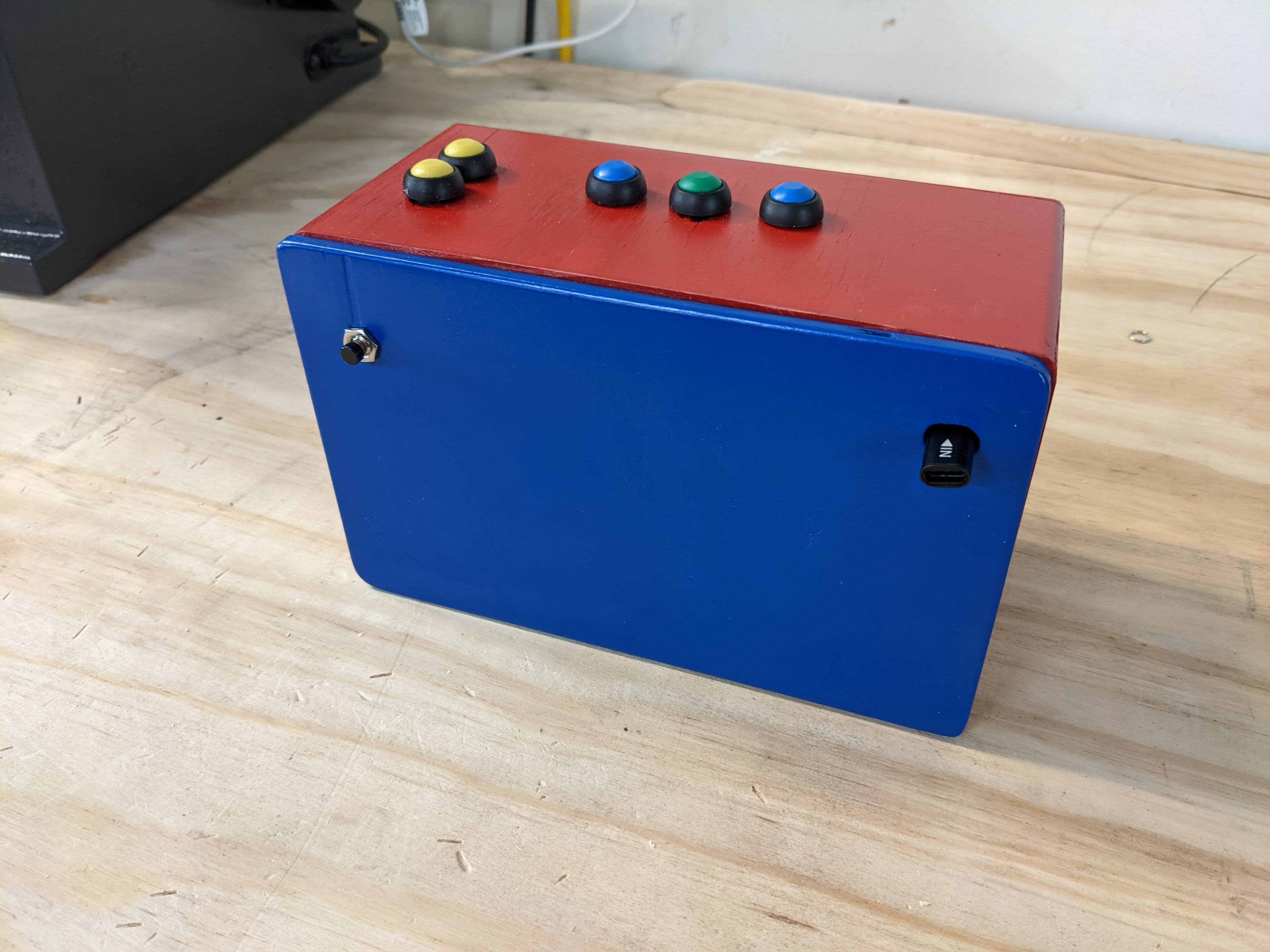
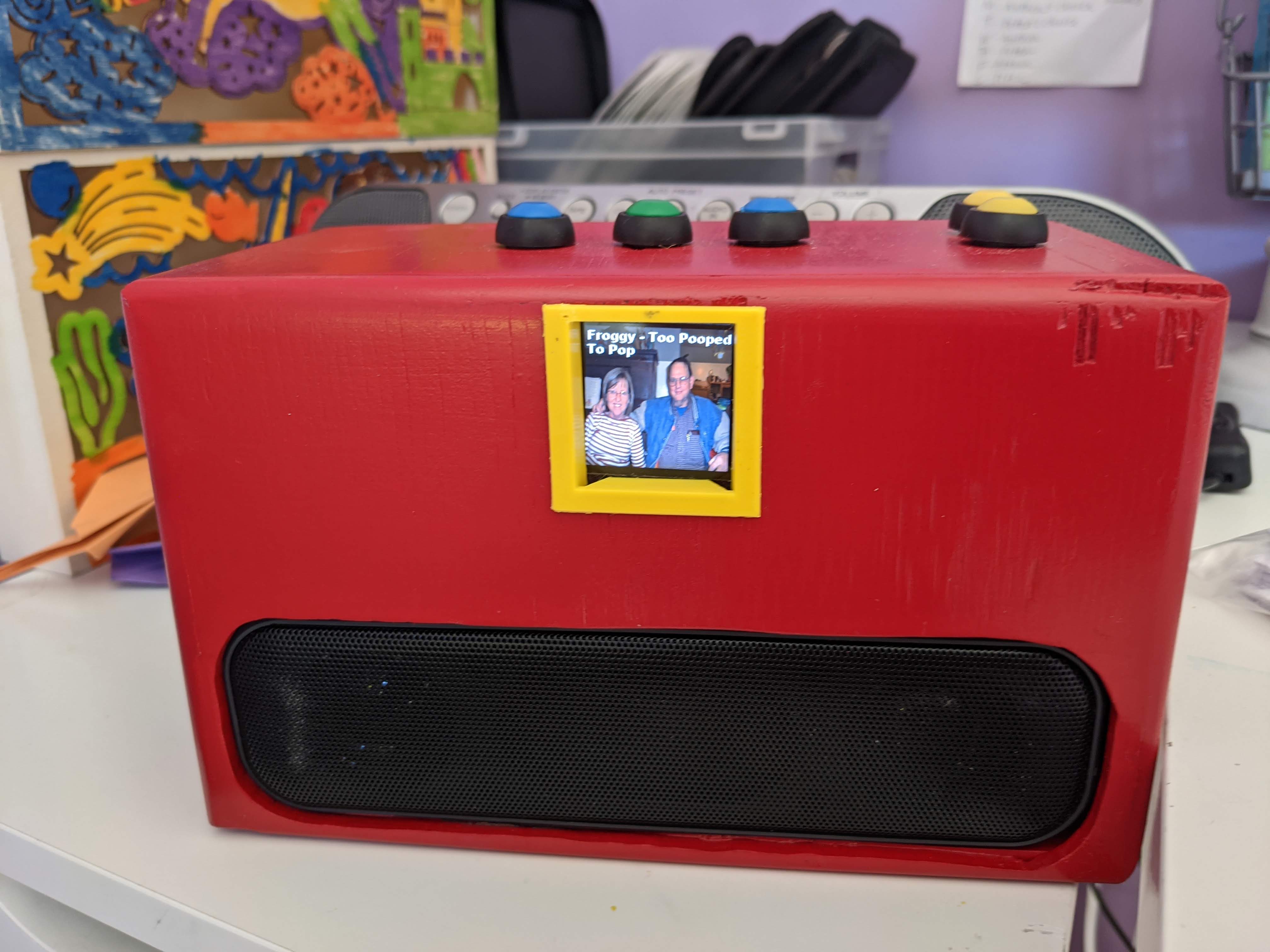 [Finished box]
RFID for MP3
As with most projects nowadays, if you can think it up, someone has probably thought of it too, finished the project, posted it online, and it looks better than I could have done. But it’s worth a try to make one anyway!
Many other people have created software and hardware solutions for creating an easy to use, modern media player. I was tempted to write the software all on my own, but I wanted to finish this project this year. :)
Here are some of the options I found:
- https://github.com/metachris/rfid-music-player
- Looked promising, but out of date.
- https://www.instructables.com/Juuke-a-RFID-Music-Player-for-Elderly-and-Kids/
- Looks simple, but not well fleshed out.
- http://rpimusicplayer.com/
- A music player, yes. A high end music player. I’d have to cobble together the RFID component.
- https://github.com/MiczFlor/RPi-Jukebox-RFID
- Perfect! It uses a Raspberry Pi, an RFID card reader, software is written and maintained currently.
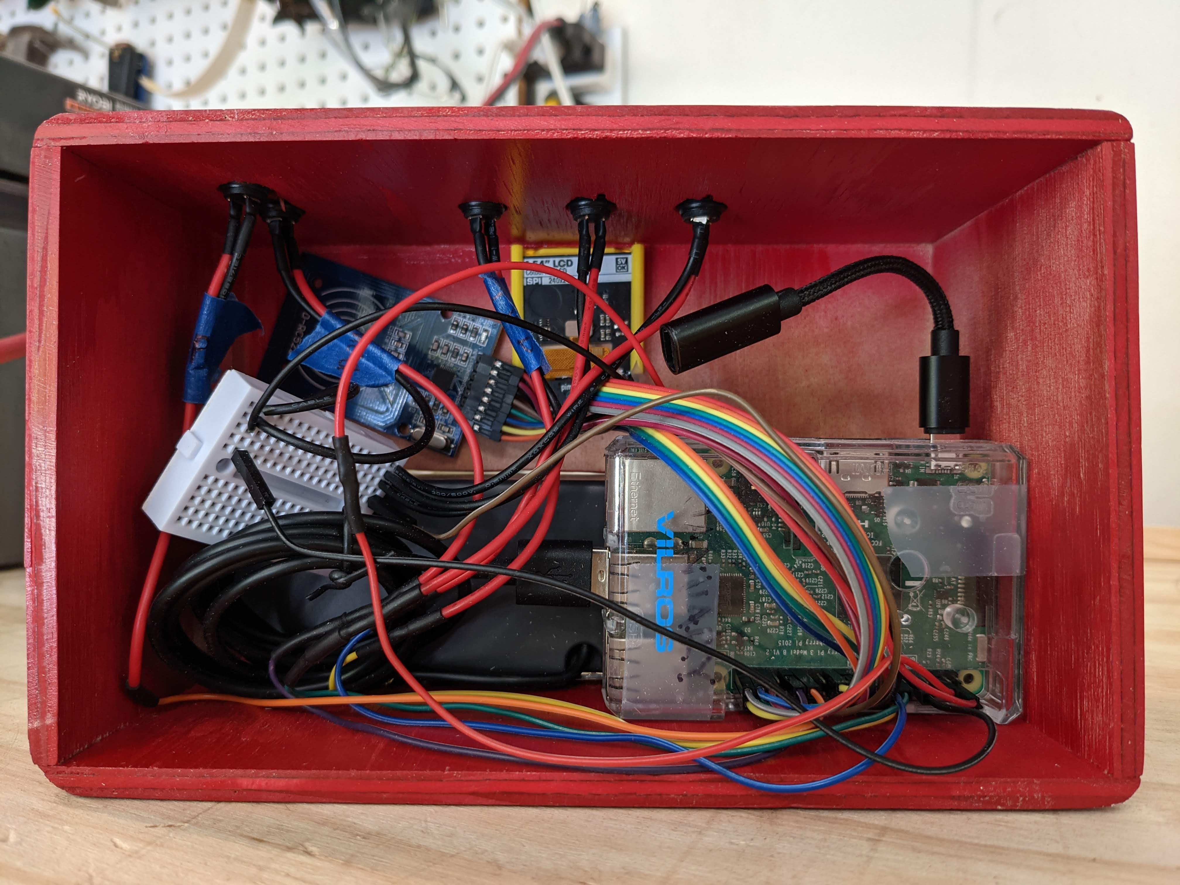
Parts
Here are the parts I used to make this project:
- 5x Momentary push buttons
- These act as the play, next, previous, volume up and volume down buttons.
- 1x Mini momentary push button
- This button starts the shutdown process for the Raspberry Pi.
- 1x USB C to USB micro adapte
- The power adapter came with a USB C to USB micro, but it made the connection to tall for the size I wanted to make, so I got this flexible one.
- 1x Raspberry Pi 4 power adapter
- After the Pi is shutdown, it still has power from the adapter, so this adapter has a switch to shut off power, too.
- 1x Pack of 20 RFID tags
- I stick these on the back of pictures of the album artwork. You tap these on the RFID card reader to change albums.
- 1x USB speakers
- This was easier than dealing with bluetooth or headphone speakers needing an amplifier.
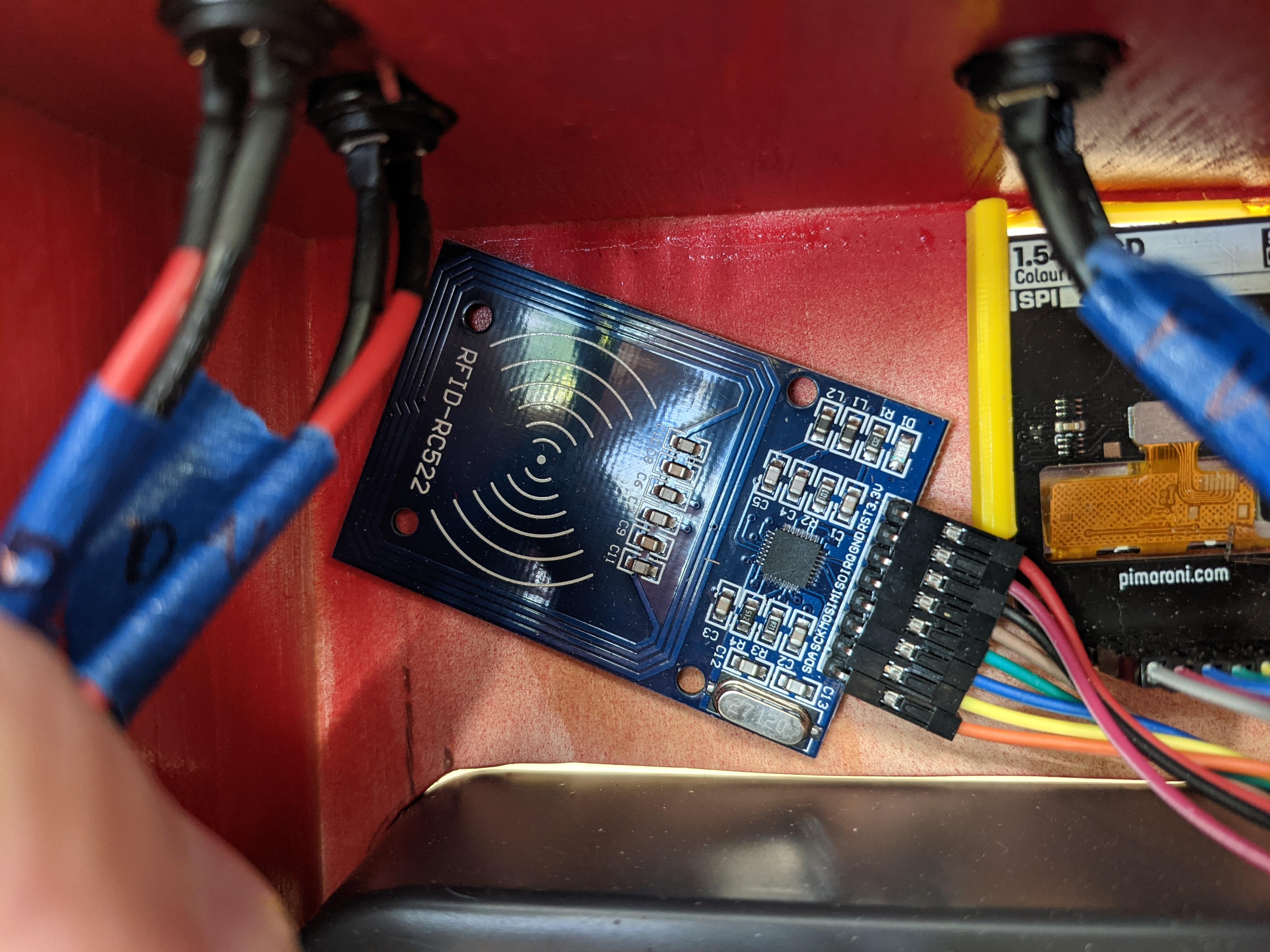
- 1x RC522 RFID card reader
- The card reader. There are also USB readers which would have made the project even easier.
- 1x Raspberry Pi 3 with mini SD card.
- I had one laying around. Good luck finding the least expensive version.
- 1x mini breadboard
- I also had one lying around. This is just to connect all the buttons to ground on the Pi.
- 1x Pack of jumper wires
- I mostly used female to female so I didn’t have to solder wires to the Pi.
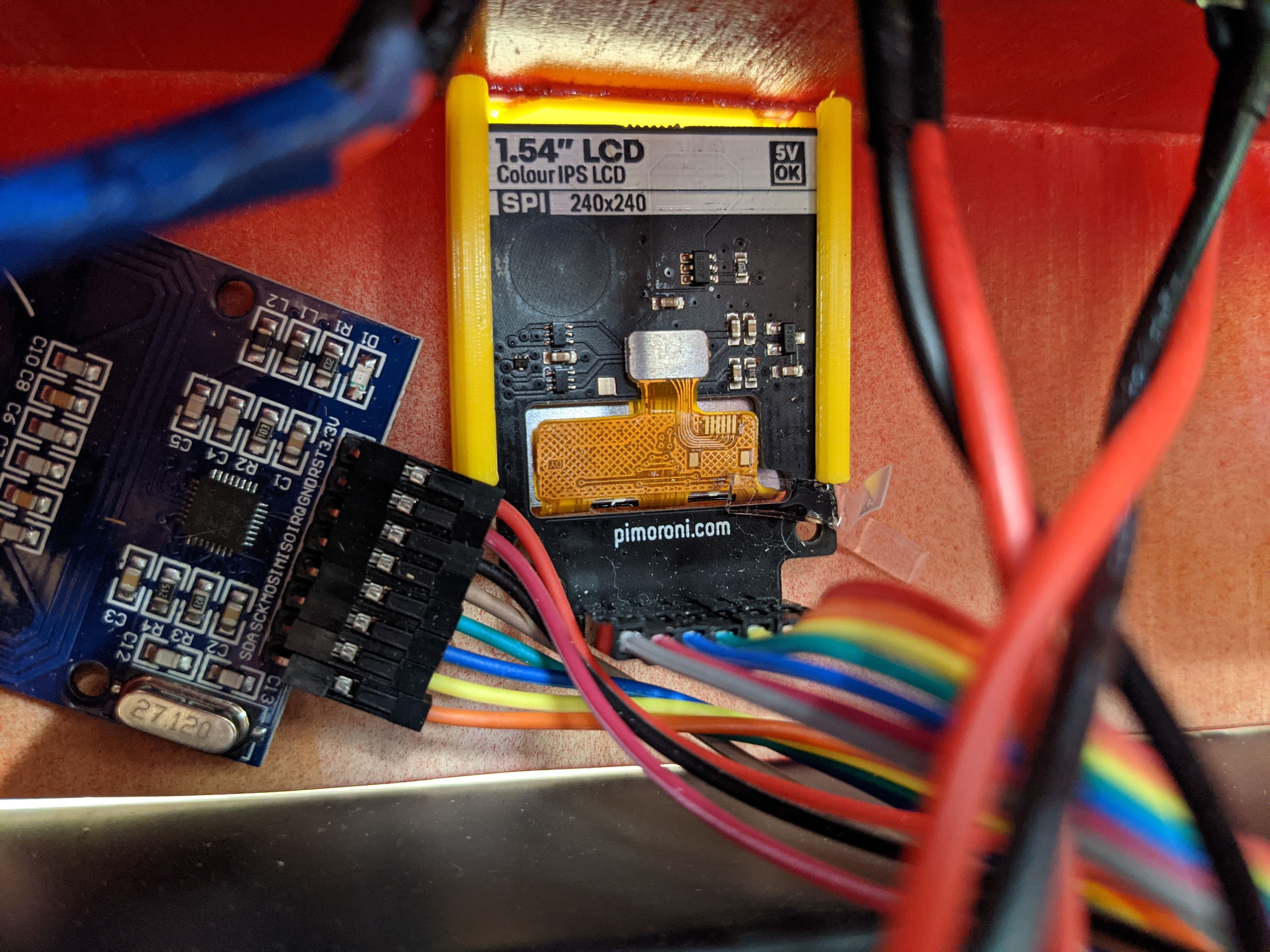
- 1x 1.54” LCD using SPI
- If I had to do over, I would have picked an LCD that plugs into HDMI. This little LCD is fun, but it basically just displays an image. If you want animation or a GUI, then you have to build it from scratch and send it frame by frame. That ruined my idea for a nice graphical way to change songs and show art work and what not.
- plywood and wood working tools
- I used some extra that I had lying around. It was not the best quality, and if I were to make this again, I would use better quality wood. The poor quality shows in the chunks of wood taken out while using the router to round off the edges. I already had all of the tools, too.
I played around with the idea of using a potentiometer to control the volume. I purchased some and even 3D printed a larger wheel. But I purchased the wrong type, and I didn’t want to figure out how to make mine work. I went the easy route and used buttons. You can see the failed attempt in the picture below with all of the wires coming off of it.
I also experimented with a holder for the RFID card. In the end I just used double sided tape to hold it in place.
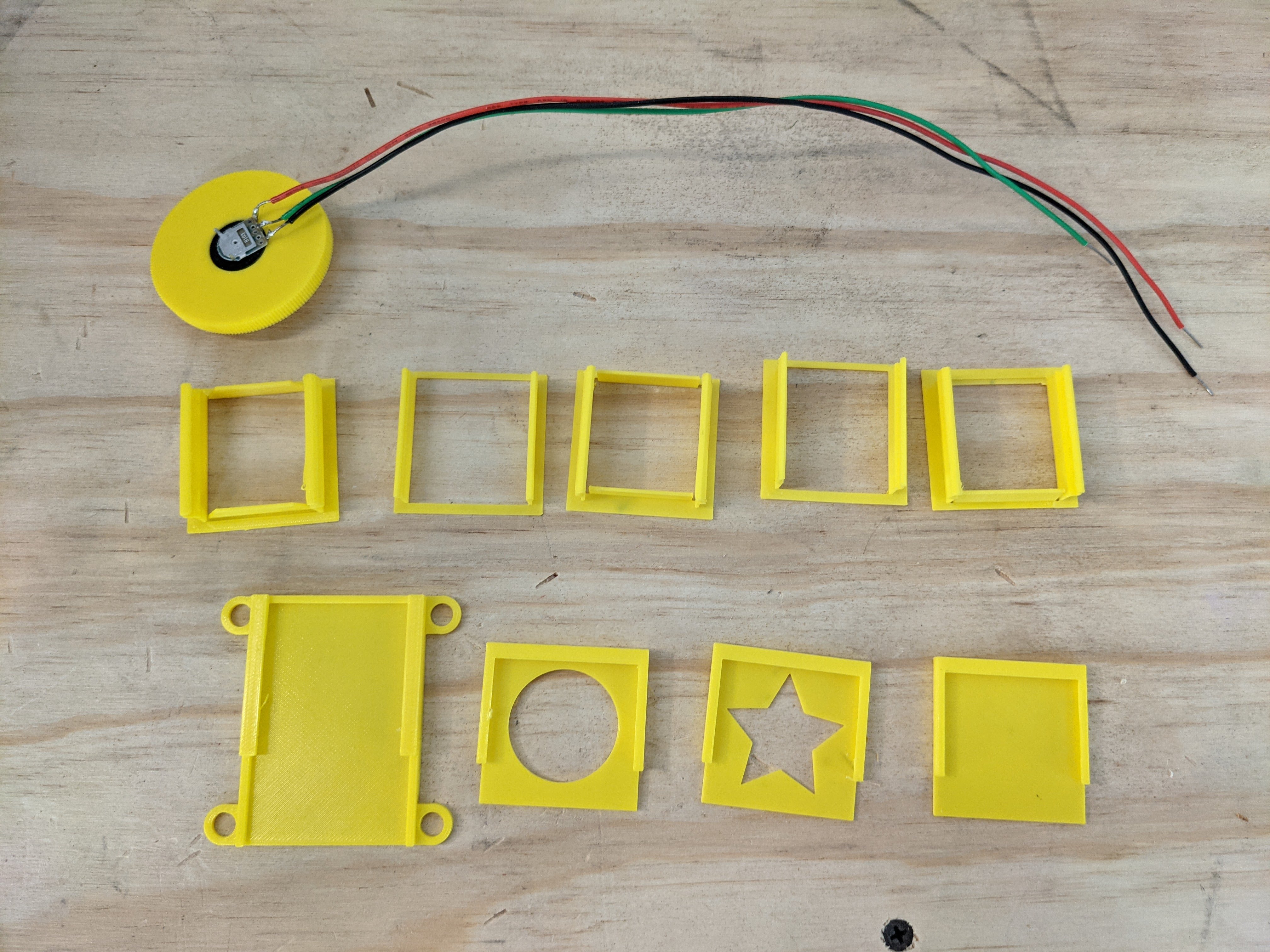 [Unused volume wheel and many variations on the LCD holder and RFID holder]
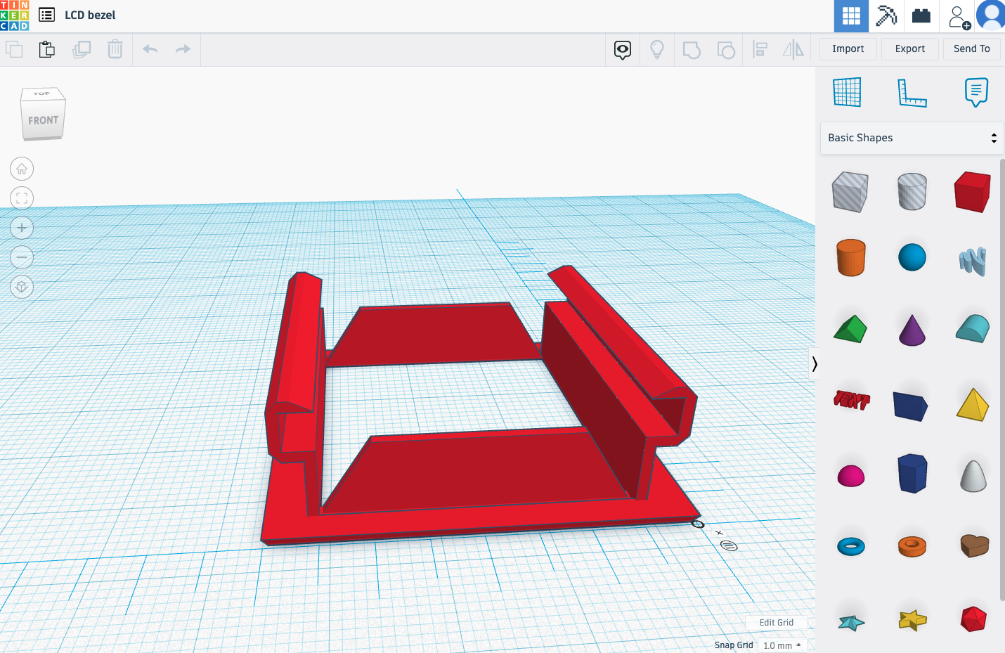
I also designed and 3D printed an LCD screen holder. This fit inside the square hole, and held the LCD in place.
Software
I used the most recent version of Raspbian OS.
Then I installed the Phoniebox/RPi Jukebox RFID software using the documentation found here https://github.com/MiczFlor/RPi-Jukebox-RFID/wiki/INSTALL-stretch#a-default-install-script-for-buster-recommended
LCD Display
The LCD display needed some custom software. I was hoping the display was more like an HDMI out that displayed the desktop natively. But it’s more like a picture frame. You send an image to it, and it displays the image. You can replicate animation by sending lots of images to the display in quick succession. (Yes, the very definition of animation.) But this must be done programmatically, like using a for loop to loop through iterations of an image.
I used Python and the ST7789 library to control the 1.54” PiMoroni SPI display.
I forked the Phoniebox/Jukebox project in order to add the LCD code. The main code for the LCD is in this repo https://github.com/ammonshepherd/RPi-Jukebox-RFID/blob/lcd/components/displays/SPI_ST7789/now_playing.py
This also requires adding a line to the bottom of the startup script to start the LCD script.
/usr/bin/python /home/pi/RPi-Jukebox-RFID/components/displays/SPI_ST7789/now_playing.py &
This causes the Python script to run continuously.
The now_playing.py script (linked above) is pretty basic. It attempts to use the files and scripts already present in the Phoniebox application, and utilizes the built in API for getting the current playing media file.
It takes the name of the file and the author, grabs the album image if there is one, then creates an image from these things and displays it to the LCD. It’s a simple static image that changes a couple of seconds after a media file is played.
Circuit
To keep track of where to plug things in, I used the wonderful Fritzing software. Here is the wiring schematic.
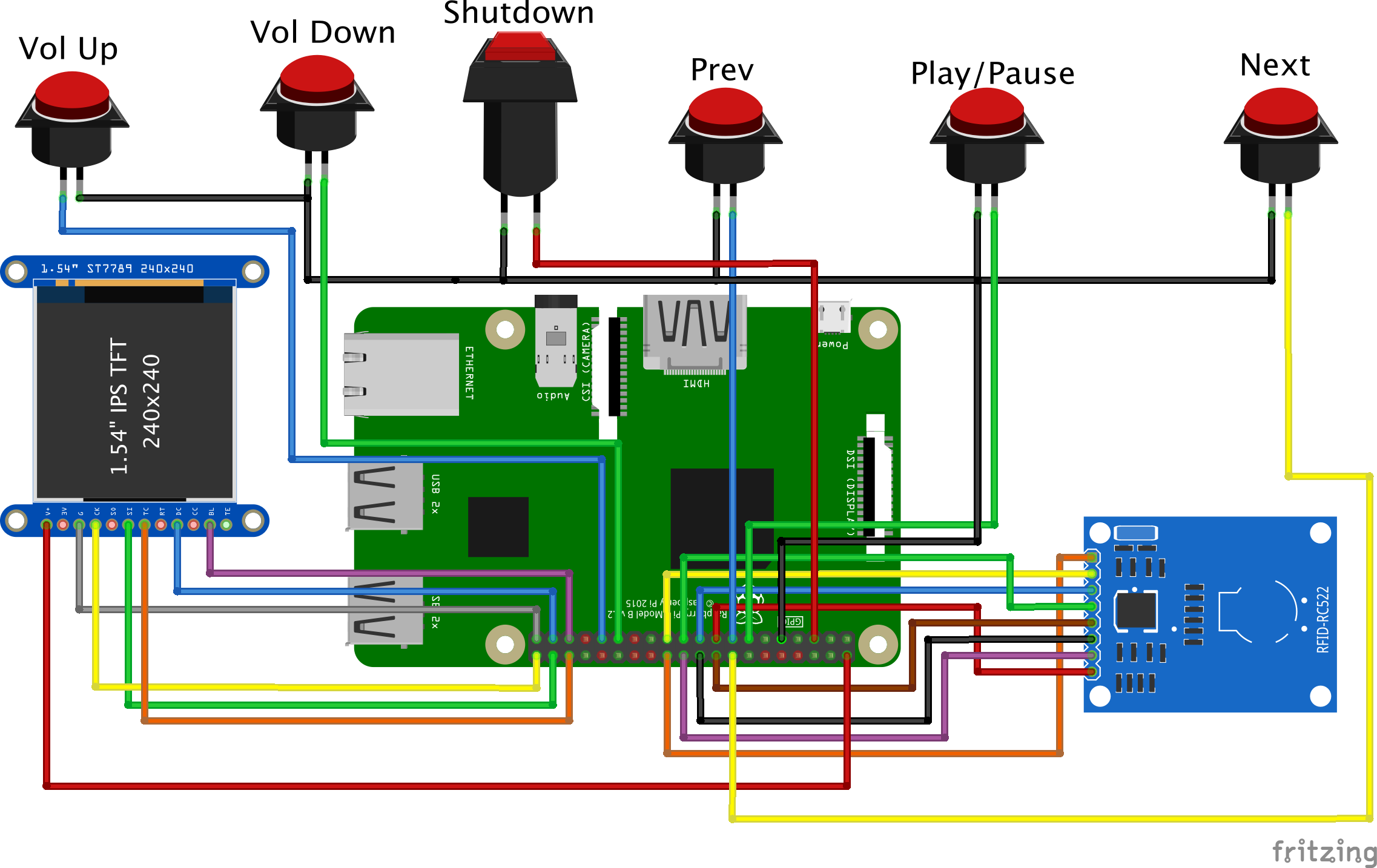
With an RFID card reader, LCD, and six buttons, nearly every port is used on the Raspberry Pi.
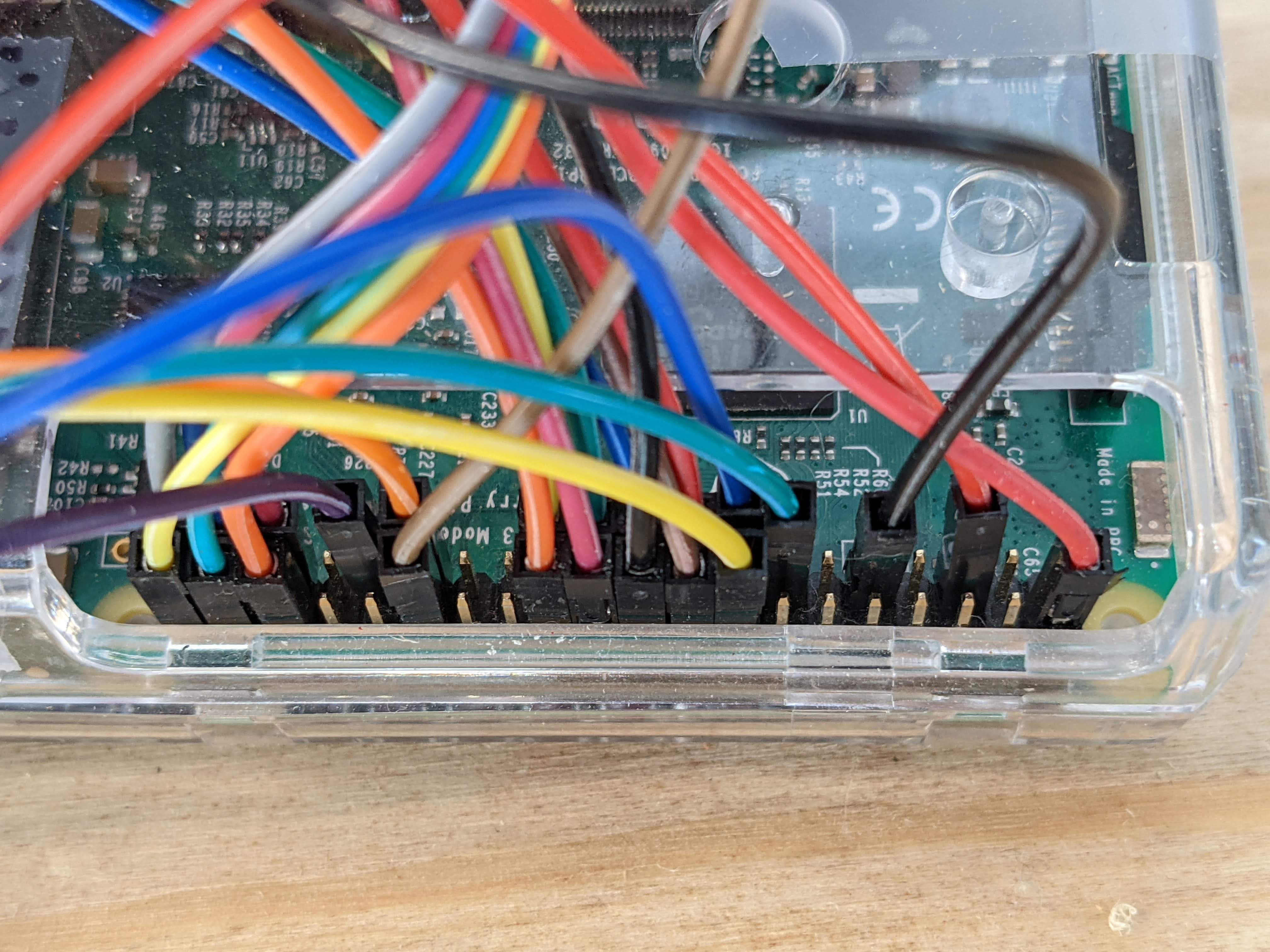
This did require some alterations of the boot config, in order to turn the GPIO pins used by the LCD into SPI pins.
RFID Card reader
This was the first thing to plug in and test. I used the default wiring suggested by the Phoniebox install instructions. Everything worked pretty smoothly.
1.54” SPI LCD
To get this LCD to work on SPI 1 (since SPI 0 is used by the RFID reader), I had to edit the /boot/config.txt file and add the following line.
# Activate SPI 1 and change pin 16 to CS for SPI LCD
dtoverlay=spi1-1cs,cs0_pin=16
The documentation from Pimoroni gives the GPIO pins to use, but I needed to adjust those since many were taken by the RFID card.
LCD   OLD      NEW
CS   -> BCM 7  -> BCM 16
SCK  -> BCM 11 -> BCM 21
MOSI -> BCM 10 -> BCM 20
DC   -> BCM 9  -> BCM 26
Buttons
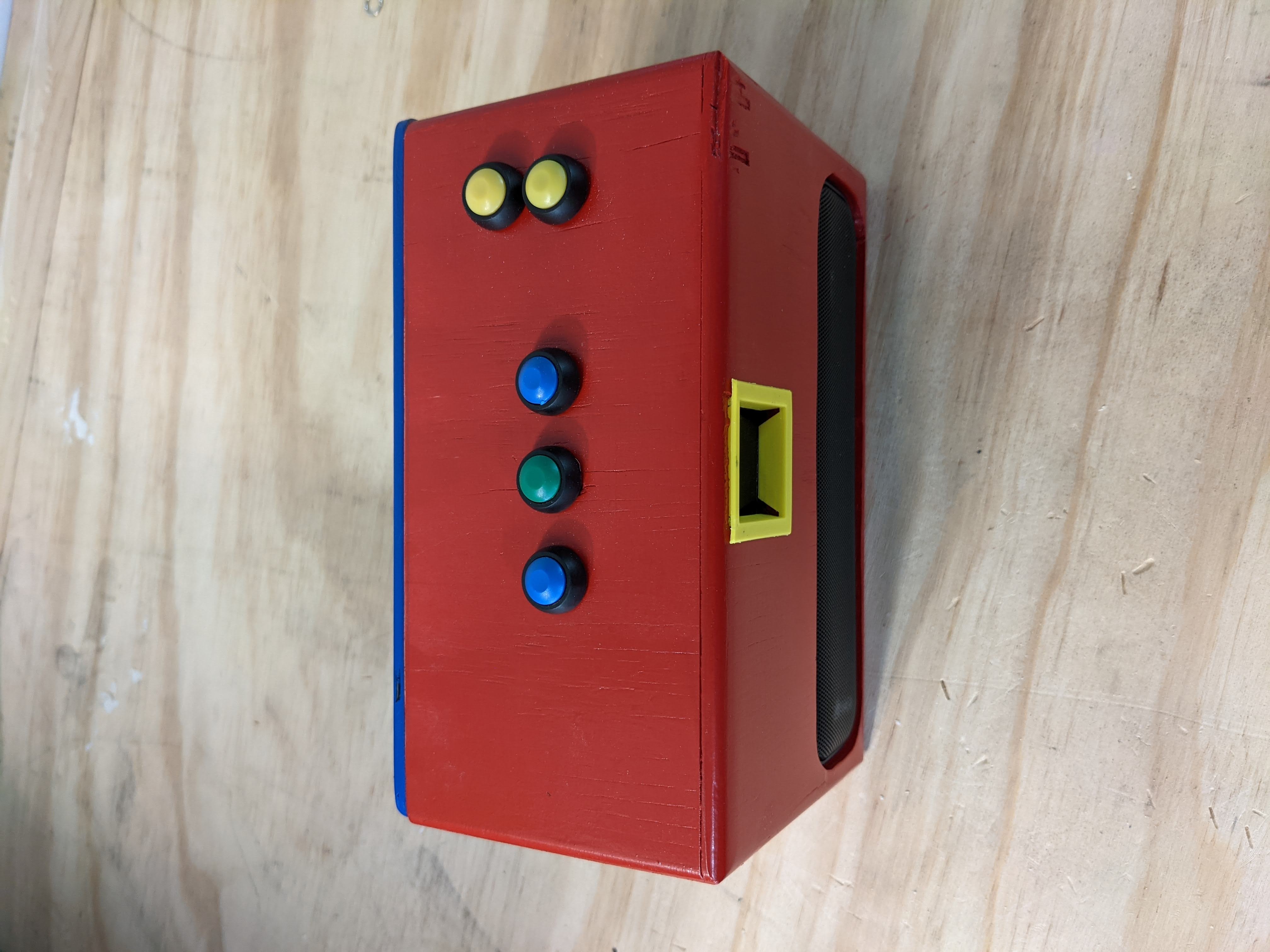
I used some mini arcade looking buttons for the control buttons. Just a simple play/pause, next, previous, and volume up and down.
I also used a small momentary button to act as a shutdown button. specs and install
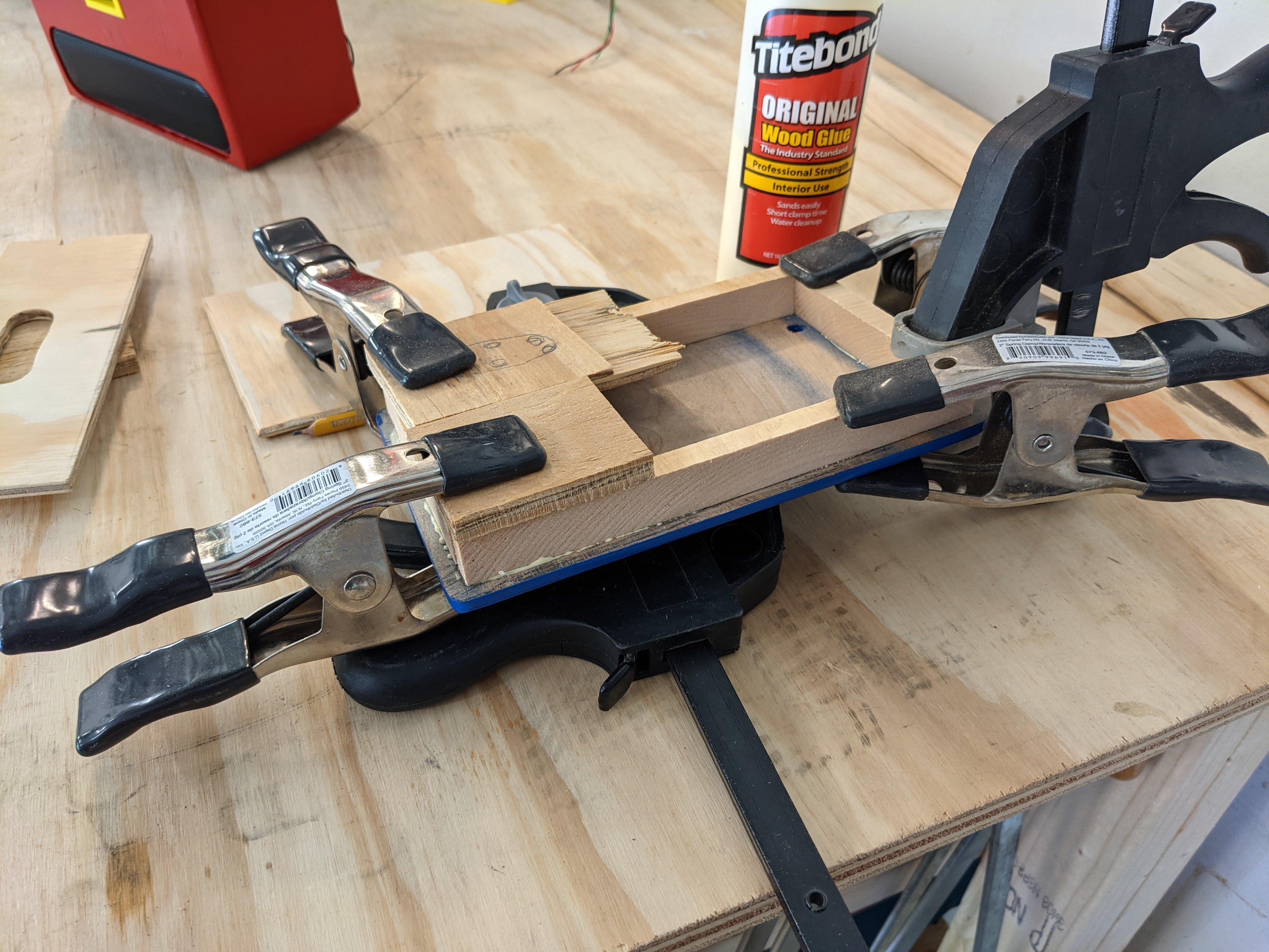
Case
I had many options here; 3D printed case, mahogany wood, cardboard, plywood, pine. I started off thinking I would make a demo case out of plywood. So I quickly constructed a simple box to hold the components. It was an exercise in learning how to cut straight lines freehand with improper tools. The first iteration was a rough approximation of a box. I took no pictures.
The second iteration was also going to be a prototype in plywood, but it ended up taking longer than expected, and I wanted to finish the project, so I opted for done is better than perfect. That is why you’ll see a big gouge on the top right of the front. It turns out that cheap plywood doesn’t work so well on a router. The main box is all just glued together, then spray painted and sealed.
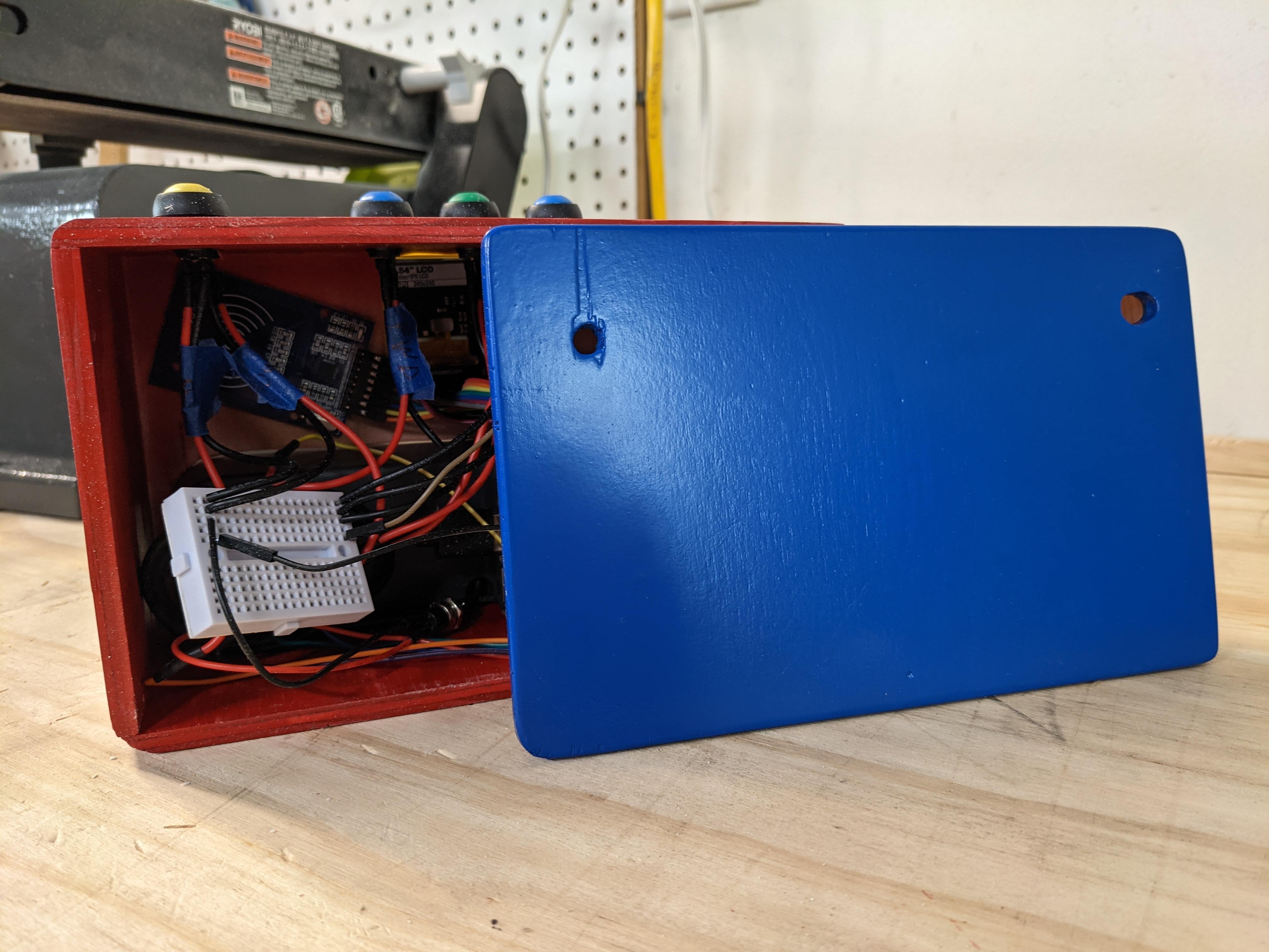
The back of the box is a piece of plywood with strips of wood glued on the back to make a snug fit within the main box to make a pretty secure pressure fitting.
The back has two holes; one for the shutdown switch, and the other for the power adapter connection.
Speaker
The USB speaker fits snuggly in the cutout in the front, and is secured with some thick double sided tape.

LCD holder
The LCD holder fits in the hole, and the LCD slides into the slots in the holder, also forming a pressure fit.
RFID Card Reader
I initially thought to 3D print a holder for the RFID card reader. But initial prototypes showed that things were fitting in a bit too snug. So it ended up being easiest to just mount the RFID card reader to the inside of the case with double sided tape.
Buttons
Three buttons for media playback, and two for volume.
Final Thoughts
This was a fun project to do. It incorporated a lot of my interests, coding, electronics, wood working. I’m not that great at any of them, but this was a good project to work on those things.
If I work on this further, I’ll fix the code to turn off the LCD when the Pi is shutdown. Currently the LCD remains powered on until power is cut to the Pi. If I had to do this over again, I’d just use a small HDMI screen instead, and have the Pi boot up the default web app.
I prefer different buttons, but these were the cheapest/best I could find for now. I’d like to look into creating my own buttons that have symbols on the top.
I would also use a USB RFID reader. Much more simple. The Phoniebox project even suggests this, as they try to be USB plug and play.
Here’s a short video of the player in action.
If you have any questions or comments, feel free to reach out to me directly at ammon@virginia.edu